
Neuro-fuzzy Sliding Mode Control for a Two Link Flexible Robot
Khedoudja Kherraz
1
, Mustapha Hamerlain
2
and Nouara Achour
1
1
Electronic Department, University of Sciences and Technology U.S.T.H.B, Bab-Ezzouar-Algiers, Algeria
2
Center of Development of Advanced Technologies (CDTA), Baba Hacen-Algiers, Algeria
Keywords: Robot Manipulator, Flexible Link, Sliding Mode, Neuro Fuzzy, Vibration Control, Chattering, Trajectory
Control, Hybrid Control, Super Twisting Algorithm.
Abstract: In most robotic applications, trajectory tracking control and vibration suppression in flexible link
manipulator is a recurring problem, due to the unknown nonlinearities and strong coupling often caused by
the presence of flexibility in the links. In order to solve this problem, a new sliding mode controller using
neural networks and fuzzy logic is presented in this paper. The stability of the proposed controller is proved
with the Lyapunov function method. The neural network is used to compensate the highly nonlinear system
uncertainties. The fuzzy logic is used to eliminate the chattering effect caused by the robust conventional
sliding mode control. The effectiveness of this control system will be compared to the performance obtained
with a second order sliding mode control which is the super twisting algorithm. Comparative simulations
show the superiority of the proposed controller regarding the second order sliding mode controller and
confirm its robustness with bounded disturbance and its ability to suppress the flexible link manipulator
vibrations.
1 INTRODUCTION
In the last few years, the dynamic proprieties and
control techniques for flexible link manipulators are
being intensively studied (Sanz and Etxebarria,
2006). They exhibit many advantages with respect to
the rigid manipulators, such as payload-to-arm ratio,
operation speed and energy consumption. But the
use of structurally flexible robotic manipulators
requires the inclusion of deformation effects due to
the flexibility in the dynamic equations which
complicates the analysis and the control design.
In a robot system, there are many uncertainties,
such as dynamic parameters, dynamic effects and
unmodeled dynamics. These uncertainties should be
taken into consideration in the control algorithm. So,
the controller of flexible manipulator must achieve
the same motion objectives as a rigid manipulator,
and it must also stabilize the vibrations. A large
number of reports have been presented, employing
the hybrid control scheme (Ho Lee and Won Lee,
2002), the radial basis function network (Tang and
Sun, 2005), the impedance control (Hui Jiang,
2005), inversion techniques (De Luca et al., 1989),
adaptive control (Yang et al., 1997) (Lin and Yeh,
1996), and VSC (variable structure control) (Fung
and Lee, 1999) (Singh and Nathan, 1991). Sliding
modes are the primary form of VSSs. The sliding
mode control is a well known approach to the
control of uncertain systems. It has received much
attention due to its ability to reject disturbances
while tracking a desired trajectory. However,
standard sliding modes are caracterized by a high-
frequncy switching of control, wich causes problems
in practical applications (so-called chattering effect).
To avoid this drawback, higher order sliding mode
(HOSM) can be used. The HOSM concept emerged
in 1980s with the motivation of tackling the
chattering phenomenon. HOSM controllers have the
capability of stabilizing around zero in finite time
not only the sliding variable, but also a number of its
time derivatives. A lot of HOSM approaches have
been studied in (Kunusch et al., 2009) (Khan et al.,
2003) (Boiko and Fridman, 2005) (Levant and
Alelishvili, 2004) (Levant, 2000) (Jimenez, 2004).
In order to reduce the chattering, other methods can
be applied such as boundary layer approach (Yeung
and Chen, 1988), fuzzy sliding mode control (Wang,
2009) and neural network sliding mode control
(Peng et al., 2006).
This paper presents the design of neuro fuzzy
sliding mode controller for flexible robotic trajectory
189
Kherraz K., Hamerlain M. and Achour N..
Neuro-fuzzy Sliding Mode Control for a Two Link Flexible Robot.
DOI: 10.5220/0004032001890195
In Proceedings of the 9th International Conference on Informatics in Control, Automation and Robotics (ICINCO-2012), pages 189-195
ISBN: 978-989-8565-21-1
Copyright
c
2012 SCITEPRESS (Science and Technology Publications, Lda.)
and vib
r
the mer
i
network
s
dynami
c
robustn
e
super t
w
sliding
m
analyse
d
Stability
Simulati
effectiv
e
p
ropose
d
robustn
e
to distur
b
2 D
Y
We con
s
of n flex
obtain t
h
introduc
e
the ma
n
links.
Let
θ
the link
that the
r
its joint
s
end-effe
c
dimensi
o
among
P
P = f(θ,
The
r
is linear
Where
matrices
as J
=
By t
a
we have
robo
t
flexible
Element
The
manipul
a
r
ation suppre
s
i
ts slinding
m
s
, in order
t
c
s, eliminate
e
ss. This co
n
w
isting algor
i
m
ode contro
l
d
for syste
m
y
of the c
ons are car
r
e
ness and
h
d
control me
t
e
ss to parame
t
b
ances.
Y
NAMIC
s
ider a flexib
l
x
ible links dri
v
h
e dynamic
m
e
of a conve
n
n
ipulator, inc
l
θ
∈ R
b
e th
e
flexible dis
p
r
obot has no
r
s
, and defin
e
c
tor positio
n
o
n workspac
e
P
, θ and δ is
n
δ).
r
elationship
a
and can be a
n
P
=
J
J
ϵR
an
d
of f with res
p
and J
=
a
king derivat
i
th en
d
-effect
o
P
=J
θ
+
J
t
We derive
d
using Lagra
n
Method).
physical
m
a
tor is shown
s
sion. The co
n
m
ode, fuzzy
t
o compensat
e
the chatteri
n
n
troller is co
m
i
th
m
, wich i
s
l
. It has bee
n
m
s with rela
t
ontrol syste
m
r
ied out to
h
igher perf
o
t
hod which i
s
t
er variations
MODEL
I
l
e robot mani
p
v
en by n rigid
m
odel, it bec
o
n
ient kinema
t
l
uding the d
e
e
joint variab
l
p
lacement ve
r
edundant deg
e
vector PϵR
n
and orien
t
e
. The kinem
a
n
onlinear, an
d
a
mong the vel
o
n
alyzed as fol
l
J
θ
+J
δ
d
J
ϵR
a
p
ect to θ and
i
on of P
wit
h
o
rs’ accelerat
i
J
δ
+J
θ
+J
d
the dyna
m
n
ge approach
m
odel of t
w
in Figure 1
n
troller integ
r
logic and n
e
e
for unmo
d
n
g and save
m
pared with
s
a second
o
n
developed
t
ive degree
m
is anal
y
demonstrate
o
rmance of
characterize
d
and insensit
i
NG
p
ulator consi
s
joints. In ord
e
o
mes necessa
r
t
ic descriptio
n
e
formation o
f
l
e vector, δϵ
R
c
tor. We ass
r
ee of freedo
m
to describe
t
ation in th
e
a
tical relatio
n
d
can be give
n
o
cities θ
, δ
a
n
l
ows:
a
re the Jaco
δ that are de
f
h
respect to t
i
on
δ
m
ic model o
f
and FEM (F
i
w
o-link fle
x
r
ates
e
ural
d
eled
the
the
o
rder
and
one.
y
zed.
the
the
d
by
i
vity
s
ting
er to
r
y to
n of
f
the
R
be
s
ume
m
on
e
the
e
n-
n
ship
n
as:
n
d P
(1)
o
bian
f
ined
t
ime,
(2)
f
the
inite
x
ible
rob
Le
M
o
M
wh
e
an
d
ce
n
se
m
ter
m
dia
g
fle
x
mo
d
ve
c
dis
p
τ
=
rot
o
W
e
ref
e
ele
m
fle
x
ma
n
att
e
so
m
3
Tr
a
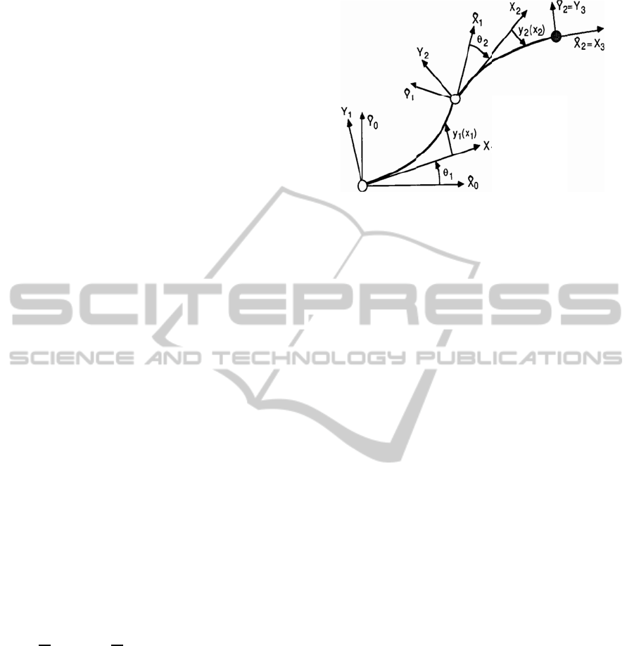
Figure 1:
A
The dynami
c
otic manipul
a
Vey, 2004)
o
rris, 2002) ca
n
M
(
θ,δ
)
θ
δ
F
(
θ,δ
)
=
τ
0
e
re M is the
d
positive de
f
n
trifugal forc
e
m
i definite li
n
m
s and ext
e
g
onal stiffne
s
x
ible modes
.
d
eled very ac
c
c
tor consists
o
p
lacements (δ
=
τ
τ
are t
h
or
-2 respectiv
e
e
take
D
The param
e
e
rence (De L
u
The control
o
m
ents bears
t
x
ibilities. Th
e
n
ipulator w
i
e
nuating the
m
e of its com
p
SLIDIN
G
a
cking error is
A
two-link flex
i
c
equation
o
a
tor with rigi
d
(
Talebi et al.
n
be given as:
+
C
θ,θ
,δ,
τ
0
=u
inertia matri
x
f
inite, C is
e
e
s, D is the
n
k damping
e
rnal disturb
a
s
s matrix th
a
Although,
c
urately. The
o
f link positi
o
11
, δ
12
, δ
21
, δ
2
2
e torques a
p
e
ly.
0
δ
+
K
δ
e
ter matrice
s
u
ca and Sicili
a
o
f a manipul
a
t
he study of
e
control obj
e
i
thin a sp
e
v
ibrations d
u
p
onents.
G
MODE
defined as:
x
ible manipulat
o
o
f a two-lin
k
d
joints (Beno
.
, 2002) (Su
b
:
δ
+
0
D
δ
+
x
, which is s
y
effect of co
r
diagonal an
d
matrix, F
i
s
a
nces and
K
a
t only affec
F
(
θ,δ
)
c
a
generalized
c
o
ns (θ
1
, θ
2
) a
n
2
).
p
plied by ro
t
=H
s
are intro
d
a
no, 1991).
a
tor formed b
y
the robot’s
e
ctive is to
m
e
cific trajec
t
u
e to the el
a
CONTR
O
o
r.
k
flexible
s
man and
b
udhi and
+
K
δ
+
(3)
y
mmetric
r
iolis and
d
positive
s
friction
K
is the
ts to the
a
nnot be
oordinate
n
d modal
t
o
r
-1 and
(4)
d
uced in
y
flexible
structural
m
ove the
t
ory but
sticity of
O
L
ICINCO2012-9thInternationalConferenceonInformaticsinControl,AutomationandRobotics
190

e=
θ
−
θ
(5)
Where θ
d
is desired joint trajectory vector.
The sliding surface variable is defined by:
s=e +
λ
e
(6)
Where λ = diag[λ
,λ
,….λ
] in wich λ
is a
positive constant for i= 1, 2….n.
The control goal is to guarantee the state
trajectories convergence to sliding surface s=0, and
keep them on the sliding surface, that is s =0.
4 SUPER TWISTING
ALGORITHM
The super twisting algorithm is one of the popular
algorithms among the second order sliding mode
algorithms (Boiko et al., 2008), (Kunusch et al,
2009). The super twisting algorithm defines the
control law u(t) as a combination of two terms
(Khan et al., 2003). The first is defined in terms of
discontinuous time derivative u
1
(t), while the second
is a continuous function of the sliding variable u
2
(t).
The super twisting algorithm is defined as follows:
u
(
t
)
=u
(
t
)
+u
(t)
(7)
where
u
={−u,
|
u
|
≻1
(8)
u
=−ωsign
(
s
)
,
|
u
|
≤1
(9)
u
|
s
|
sign
(
s
)
,
|
s
|
>s
(10)
u
=−
λ
|
s
|
sign
(
s
)
,
|
s
|
≤s
(11)
And sufficient conditions for finite time
convergence are:
ω>
Ф
Γ
≻0
(12)
λ
=
4ФΓ
(ω + Ф)
Γ
(ω − Ф)
(13)
where , λ and ρ are variable controller parameters,
∅ is positive norm bound on the smooth uncertain Ф,
Γ
and Γ
are lower and upper positive bounds on
the smooth uncertain function, γ. The choice of
ρ=0.5 assures that sliding order 2 is achieved
(Levant, 1993).
The super twisting algorithm in equation (7) can
be simplified as follows:
u
(
t
)
=−
λ
|
s
|
sign
(
s
)
+u
(14)
u
=−ωsign
(
s
)
(15)
This control algorithm does not need any
information on the time derivatives of the sliding
variable nor any explicit knowledge of other system
parameters.
5 DESIGN OF NEURO FUZZY
SLIDING MODE CONTROL
We define a Lyapunov function:
V=
1
2
s
Ms
(16)
V
=s
Ms +
1
2
s
M
s
(17)
Since s
M
−2Cs=0
(18)
Then
V
=s
(
Ms +Cs
)
= s
[(u − M
(
q
−λe
)
−C
(
q
−λe
)
−H−F
]
=s
(u +
(
Mλe +Cλe
)
−F
−Mq
−Cq
− H) (19)
u is chosen as:u= −μ − k
sign(s)
(20)
where
μ=M
λ
e +C
λ
e
(21)
B=Mq
+Cq
+H)
(22)
Then
V
=s
(−F
−B−k
sign
(
s
)
)
(23)
The sliding condition V
<0 can be satisfied if k
is
selected such that:
k
>
|
F
+B
|
(24)
In order to guarantee that the system tracking
error is quickly convergent k
should be chosen
sufficiently large.
When s>0,
s
(−F
−B−k
sign
(
s
)
)<0
(25)
When s<0,²
s
−F
−B−k
sign
(
s
)
<0
(25)
Thus
V
=s
−F
−B−k
sign
(
s
)
<0
(27)
This guarantees that hitting condition is satisfied.
Neuro-fuzzySlidingModeControlforaTwoLinkFlexibleRobot
191

In this paper, a neuro-fuzzy is used to
compensate the uncertainty F
in the robot system
reel-time. A five layer neuro-fuzzy structure is
applied. It can be described in detail as below:
Where x=(x
,x
) is the input of the neuro-fuzzy.
y=(y
,y
) is the output of the neuro-fuzzy.
Layer 1:
The nodes in this layer represent membership
functions.
O
=μ
(x), for i=1. ...3, j=1……3.
(28)
O
=μ
(x), for i=4. ...6, j=1……3.
(29)
Where:
and
are triangular fuzzy sets.
Layer 2:
O
= μ
(
x
)
μ
(
x
)
=W
,j=1……9.
(30)
Layer 3:
O
=
W
∑
W
=V
(31)
Layer 4:
O
=
1−e
1+e
=Z
(32)
Layer 5:
O
=
∑
T
O
(33)
k=1…2
T
is the connection weight
T=
T
T
…….. T
T
T
…….. T
(34)
The output of the five layer neuro fuzzy can be
rewritten as follows:
Y
=TZ
(35)
The system uncertainty F
can be described as
follows:
F
=TZ+ε
(36)
ε is the approximation error.
If the neuro fuzzy algorithm satisfies:
T
=−
γ
sZ
(37)
Where γ>0.
The output of the controller is designed as:
u=−s−μ+
(
1+
γ
)
TZ − B − k
sign(s)
(38)
But k
can cause chattering due to the sign function.
In order to eliminate the chattering, we replace the
control k
sign(s) by a fuzzy gain k
. Then,
V
=s
(−F
−B−k
)
(39)
In order to make V
<0 and guarantee the sliding
mode condition, the fuzzy rules can be decided as
follows:
IF s is NB THEN k
is NB
IF s is N THEN k
is N
IF s is Z THEN k
is Z
IF s is P THEN k
is P
IF s is PB THEN k
is PB
Then
u=−s−μ+
(
1+
γ
)
TZ − B + k
(40)
6 SIMULATION RESULTS
In order to demonstrate the superior performance of
the two methods, a simulation example of a two–link
flexible robotic manipulator is also considered. The
function of the desired trajectories can be expressed
as:
θ
(
t
)
=
θ
+
(
)
(
−sin
)
(41)
Where θ(t) is the desired tracking curve. θ
is the
initial value of θ(t).
We assume the disturbance as:
d
(
t
)
=w
(
t
)
sin (2 πt)
(42)
Where w(t) is a Gaussian distributed randon signal
with mean zero and standard deviation σ.
The figures compare the results obtained with the
super twisting algorithm and neuro fuzzy sliding
mode control for tip position control when the
flexible manipulator was commanded to move from
an initial position of 0 rad to a target tip position of
0.5 rad. From the tip deflection trajectories shown in
figures (2) and (3), it can be seen that deflection is
less with the neuro fuzzy sliding mode control than
Super Twisting algorithm. The first and second
mode of vibration has smaller amplitude with the
neuro fuzzy sliding mode compared to the super
twisting. Even more important, it should be noted
that the oscillations of elastic modes are attenuated
quickly with the neuro fuzzy sliding mode control.
Control profiles of the controllers are shown in
ICINCO2012-9thInternationalConferenceonInformaticsinControl,AutomationandRobotics
192
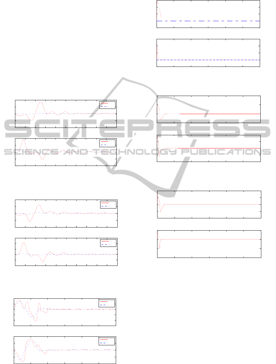
figure (4). Initially, the control torque rises to a
maximum of 0.6 and 0.8 respectively, and in all
cases, the control torque eventually becomes zero
when the desired tip displacement is achieved and
the vibration is completely damped out.
Figure (5) shows the position error for the two
methods. The tip position trajectory with the method
of Super Twisting algorithm has a law rise time but
overshoots more than the method of neuro fuzzy
sliding mode control.
Figures (6) and (7) show the velocity error for
the two methods. It can be seen that the tracking of
the desired velocity is better with the neuro fuzzy
sliding mode control.
Figure 2: First mode and second mode deflection
trajectories (link 1).
Figure 3: First mode and second mode deflection
trajectories (link 2).
Figure 4: Control torque.
Figure 5: Position error σ=0.
Figure 6: Velocity error with Super Twisting algorithm.
Figure 7: Velocity error with neuro fuzzy sliding mode
control.
Figures (8) to (11) show the position error for the
two controllers with the variation of the
perturbation. The neuro fuzzy sliding mode is more
robust than Super Twisting algorithm. It can be seen
that the tip position exhibits better tracking of the
desired trajectory with the neuro fuzzy sliding mode
control. For σ = 0.1 to 100, the error position is
acceptable with the two methods. But since
= 120, the desired trajectory with Super Twisting
algorithm is completely divergent. For σ = 180, the
error position with the neuro fuzzy sliding mode
control start to be high.
0 0.5 1 1.5 2 2.5 3 3.5 4 4.5 5
-0.04
-0.02
0
0.02
0.04
Temps (sec)
First mode deflection art(1)
0 0.5 1 1.5 2 2.5 3 3.5 4 4.5 5
-0.02
-0.01
0
0.01
0.02
Temps (sec)
Second mode deflection art(1), (m)
ST
MNF
ST
MNF
0 0.5 1 1.5 2 2.5 3 3.5 4 4.5 5
-0.01
-0.005
0
0.005
0.01
Temps (sec)
First mode deflection art(2)
0 0.5 1 1.5 2 2.5 3 3.5 4 4.5 5
-0.02
-0.01
0
0.01
0.02
0.03
Temps (sec)
Second mode deflection art(2), (m)
ST
MNF
ST
MNF
0 1 2 3 4 5 6
-1.5
-1
-0.5
0
0.5
1
Temps (s ec)
Control torque art(1), (N.m)
0 1 2 3 4 5 6
-1
-0.5
0
0.5
1
Temps (s ec)
Control torque art(2), (N.m)
ST
MNF
ST
MNF
0 1 2 3 4 5 6
-5
0
5
10
15
x 10
-3
Temps (sec)
Erreur art(1)
0 1 2 3 4 5 6
-5
0
5
10
15
x 10
-3
Temps (sec)
erreur art(2), (rad)
0 1 2 3 4 5 6
-5
0
5
10
x 10
-6
Temps (sec)
Link 1:Velocity error(rad/s)
0 1 2 3 4 5 6
-2
-1
0
1
2
x 10
-5
Temps (sec)
Link 2:Velocity error(rad/s)
0 1 2 3 4 5 6
-4
-2
0
2
4
x 10
-6
Temps (sec)
Link 1:Velocity error(rad/s)
0 1 2 3 4 5 6
-2
-1
0
1
x 10
-5
Temps (sec)
Link 2:Velocity error(rad/s)
Neuro-fuzzySlidingModeControlforaTwoLinkFlexibleRobot
193
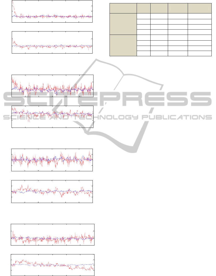
Figure 8: Position error σ= 6.
Figure 9: Position error σ= 20.
Figure 10: Position error σ= 120.
Figure 11: Position error σ= 180.
Table 1: Comparaison between the two controllers.
Control
σ
Rise
time
Precision Robustness
Super
Twisting
algorithm
6 0.1 0.015 Good
20 0.5 0.02 Good
120 Bad 0.6 Bad
180 Bad Bad Very bad
Neuro Fuzzy
Sliding Mode
Control
6 0.1 10
-7
Very good
20 0.2 10
-5
Very good
120 0.5 0.1 Good
180 0.6 0.2 Good
7 CONCLUSIONS
Due to nonlinearities and uncertainties, the dynamic
characteristics of flexible-link manipulator are very
difficult to obtain precisely. In order to achieve high
precision position control and suppress the
vibrations, a combined control strategy based on the
concept of sliding mode control, neural network and
fuzzy logic is proposed in this paper. Neural network
is employed to mimic an equivalent control law in
the sliding mode control and approximate the
uncertainties and disturbances; fuzzy logic is
developed to eliminate the chattering phenomenon.
This controller is compared with the super twisting
algorithm. The simulation results show that the two
methods can eliminate the phenomenon chattering
greatly, and confirm that the proposed controller
achieves efficient positioning and vibration
suppression performances. The neuro fuzzy sliding
mode controller is more robust than Super Twisting
algorithm.
REFERENCES
Sanz A., Etxebarria V., 2006. Experimental Control of a
Two-Dof Flexible Robot Manipulator by Optimal and
Sliding Methods. Intell Robot Syst.
Ho Lee S., Won Lee C., 2002. Hybrid control Scheme for
robust tracking of two-link-Fexible manipulator.
Journal of intelligent and robotic system.
Tang Y., Sun F., Sun Z., 2005. Tip tracking of a Flexible-
link manipulator with radial basis Function and fuzzy
system. Springer- Verlag Berlin Aeidlberg.
Hui Jiang Z., 2005. Impedance control of flexible Robot
arm with parametric uncertainties. Journal of
intelligent and robotic system.
De Luca, A., Lucibello, P., and Ulivi, G., 1989, Inversion
techniques for trajectory control of flexible robot arms.
J. Robotic Systems 6(4), 325–344.
0 1 2 3 4 5 6
-5
0
5
10
15
x 10
-3
Temps (sec)
Link 1:Position error, (rad)
0 1 2 3 4 5 6
-0.01
0
0.01
0.02
Temps (sec)
Link 2:Position error, (rad)
0 1 2 3 4 5 6
-0.01
0
0.01
0.02
Temps (sec)
Link 1:Position error, (rad)
0 1 2 3 4 5 6
-0.04
-0.02
0
0.02
Temps (sec)
Link 2:Position error, (rad)
0 1 2 3 4 5 6
-0.4
-0.2
0
0.2
0.4
Temps (sec)
Link 1:Position error, (rad)
0 1 2 3 4 5 6
-1
-0.5
0
0.5
1
Temps (sec)
Link 2:Position error, (rad)
0 1 2 3 4 5 6
-0.5
0
0.5
1
Temps (sec)
Link 1:Position error, (rad)
0 1 2 3 4 5 6
-2
-1
0
1
2
Temps (sec)
Link 2:Position error, (rad)
ICINCO2012-9thInternationalConferenceonInformaticsinControl,AutomationandRobotics
194

Yang, J. H., Lian, F. L., and Fu L. C., 1997. Nonlinear
adaptive control for flexible-link manipulators, IEEE
Trans. Robotics Automat. 13(1), 140–148.
Lin, L. C. and Yeh, S. L., 1996. A composite adaptive
control with flexible quantity feedback for flexible-
link manipulators, J. Robotic Systems 13(5), 289–302.
Fung E. H. K., Lee C. K. M., 1999. Variable structure
tracking control of a single-link flexible arm using
time-varying sliding surface, J. Robotic Systems
16(12), 715–726.
Singh S. N. and Nathan, P. J., 1991. Sliding mode control
and elastic mode stabilization of a robotic arm with
flexible links, ASME J. Dyn. Systems Meas. Control
113, 669–676.
Kunusch C., Puleston P. F., Mayosky M. A., and Riera J.,
2009. Sliding Mode Strategy for PEM Fuel Cells
Stacks Breathing Control Using a Super-Twisting
Algorithm. IEEE Transactions on Control Systems
Technology, VOL. 17, NO. 1.
Khan M. K., Goh K. B., and Spurgeon S. K., 2003.
Second Order Sliding Mode Control of a Diesel
Engine. Asian Journal of Control, Vol. 5, No. 4, pp.
614-619.
Boiko I. and Fridman L., 2005. Analysis of Chattering in
Continuous Sliding-Mode Controllers. IEEE
Transactions on Automatic Control, VOL. 50, NO. 9.
Levant A. and Alelishvili L., 2004. Transient adjustment
of high-order sliding modes. in Proc. of the 7th
Scientific Workshop “Variable Structure Systems
VSS'2004”, Vilanova, Spain, September 6-8.
Levant A., Pridor A., Gitizadeh R., Yaesh I., and Ben-
Asher J. Z., 2000. Aircraft Pitch Control Via Second
Order Sliding Technique. AIAA Journal of Guidance,
Control and Dynamics, 23(4), 586-594.
Jimenez T. S., 2004. Diving control a torpedo
Autonomous Underwater Vehicle. Doctorate thesis,
LIRMM - University of Montpellier II.
Yeung K. S. and Chen Y. P., 1988. A new Controller
design for manipulators using the theory of variable
structure systems. [J]. IEEE Trans.Automat. Control.
Wang W., 2009. Adaptive Fuzzy Sliding Mode Control
for Inverted Pendulum. Proceedings of the Second
Symposium International Computer Science and
Computational Technology (ISCSCT ’09).
Peng J., Wang Y., Wei S. and Liu Y., 2006. A neural
network sliding mode controller with application to
robotic manipulator. Proceedings of the 6th world
congress on intelligent control and automation, June
21- 23, Dalian, China.
Benosman M. and Le Vey G., 2004. Control of flexible
manipulators: A survey. Robotica (2004) volume 22,
pp. 533–545. Cambridge University Press
Talebi H. A., Khorasani K. and Patel R. V., 2002.
Tracking control of a flexible-link Manipulator using
neural networks: experimental results. Robotica (2002)
volume 20, pp. 417–427. Cambridge University Press.
Subudhi B., Morris A. S., 2002. Dynamic modelling,
simulation and control of a manipulator with flexible
links and joints. Robotics and Autonomous Systems 41,
257–270.
De Luca A. and Siciliano B., 1991. Closed- form dynamic
model of planar multilink lightweight robots. IEEE
Transactions on systems, MAN, and cybernetics, vol
21, NO, 4.
Boiko I., Castellanos I. and Fridman L., 2008. Analysis of
response of second-order sliding mode controllers to
external inputs in frequency domain. Int. J. Robust
Nonlinear Control.
Levant, A., 1993. Sliding order and sliding Accuracy in
sliding model control, International Journal of
Control, vol.58, no.6, pp.1247-1263.
Neuro-fuzzySlidingModeControlforaTwoLinkFlexibleRobot
195
