
Proposal to Improve the Requirements Process
through Formal Verification using Deductive Approach
Radosław Klimek
AGH University of Science and Technology, al. A. Mickiewicza 30, 30-059 Krakow, Poland
Keywords:
Requirements Engineering, Use Case Diagram, Use Case Scenario, Activity Diagram, Formal Verification,
Deductive Reasoning, Semantic Tableaux Method, Temporal Logic, Workflows, Design Patterns, Generating
Formulas.
Abstract:
The work concerns gathering requirements and their formal verification using deductive approach. This ap-
proach is based on the semantic tableaux reasoning method and temporal logic. The semantic tableaux method
is quite intuitive and has some advantages over traditional deduction strategies. System requirements are gath-
ered using some UML diagrams. Requirements engineering based on formal analysis and verification might
play an essential role in producing the correct software since this approach increases reliability and trust in
software. Deductive inference is always the most natural for human beings and is used intuitively in everyday
life. A use case, its scenario and its activity diagram may be linked to each other during the process of gather-
ing requirements. When activities and actions are identified in the use case scenario then their workflows are
modeled using the activity diagram. Organizing the activity diagram workflows into design patterns enables
the automation of the process of generating logical specifications. The automation of this process is crucial
and constitutes a challenge in the whole deductive approach. Temporal logic properties and formulas may be
difficult to specify by inexperienced users and this fact can be a significant obstacle to the practical use of
deduction-based verification tools. The approach presented in this paper attempts to overcome this problem.
Automatic transformation of workflow patterns to temporal logic formulas is proposed. These formulas con-
stitute logical specifications of requirements models. The architecture of an automatic and deduction-based
verification system is proposed. Applying this innovative concept results in the reduction of software develop-
ment costs as some errors might be addressed in the software requirements phase and not inthe implementation
or testing phases.
1 INTRODUCTION
1.1 Preliminaries
Software modeling enables better understanding of
a domain problem and a developed system. Better
software modeling is key in obtaining reliable soft-
ware. Requirements engineering is an important part
of software modeling. The process of gathering re-
quirements understood as an extra layer of abstraction
improves not only the reliability of the software de-
velopment phase but also enhances corporation com-
munication, planning, risk management and enables
cost reductions. System requirements are descriptions
of delivered services in the context of operational
constraints. Identifying software requirements of the
system-as-is, gathering requirements and the formu-
lation of requirements by users enables the identifica-
tion of defects earlier in a life cycle. Thinking of
requirements must precede the code generating act.
UML, i.e. Unified Modeling Language (Rumbaugh
et al., 1999; Pender, 2003), which is ubiquitous in
the software industry can be a powerful tool for the
requirements engineering process. UML use cases
are central to UML since they strongly affect other
aspects of the modeled system and, after joining the
activity diagrams, may constitute a good instrument
to discover and write down requirements. UML also
appears to be an adequate and convenient tool for
the documentation of the whole requirements pro-
cess. What is more, the use case and activity dia-
grams may also be used in a formal-based analysis
and the verification of requirements. Formal methods
in requirements engineering may improve the process
through a higher level of rigor which enables a bet-
ter understanding of the domain problem and deduc-
105
Klimek R..
Proposal to Improve the Requirements Process through Formal Verification using Deductive Approach.
DOI: 10.5220/0004001901050114
In Proceedings of the 7th International Conference on Evaluation of Novel Approaches to Software Engineering (ENASE-2012), pages 105-114
ISBN: 978-989-8565-13-6
Copyright
c
2012 SCITEPRESS (Science and Technology Publications, Lda.)

tive verification of requirements. Temporal logic is a
well established formalism for describing properties
of reactive systems. It may facilitate both the sys-
tem specifying process and the formal verification of
non-functional requirements which are usually diffi-
cult to verify. The semantic tableaux method, which
is a proof formalization for deciding satisfiability and
which might be more descriptively called “satisfia-
bility trees”, is very intuitive and may be considered
goal-based formal reasoning to support requirements
engineering.
Maintaining software reliability seems difficult.
Formal methods enable the precise formulation of im-
portant artifacts arising during software development
and the elimination of ambiguity and subjectivity in-
consistency. Formal methods can constitute a foun-
dation for providing natural and intuitive support for
reasoning about system requirements and they guar-
antee a rigorous approach in software construction.
There are two important parts to the formal approach,
i.e. formal specification and formal reasoning, though
both are quite closely related to each other. Formal
specification introducesformal proofs which establish
fundamental system properties and invariants. Formal
reasoning enables the reliable verification of desired
properties. There are two well established approaches
to formal reasoning and information systems verifica-
tion (Clarke et al., 1996). The first is based on the
state exploration and the second is based on deduc-
tive inference. During recent years there was par-
ticularly significant progress in the field of state ex-
ploration also called “model checking” (Clarke et al.,
1999). However, model checking is an operational
rather than analytic approach. Model checking is a
kind of simulation for all reachable paths of compu-
tation. Unfortunately, the inference method is now
1. USE CASE DIAGRAMS
2. USE CASE SCENARIOS
3. ACTIVITY DIAGRAMS
4. LOGICAL SPEC. GENERATION
5. DEFINING PROPERTIES
6. REASONING PROCESS
Software maturity
FORMALIZATION
Figure 1: Software requirements modeling and verification.
far behind state exploration for several reasons, one
of which is the choice of a deductive system. How-
ever, a more important problem is a lack of methods
for obtaining system specifications which are consid-
ered as sets of temporal logic formulas and the au-
tomation of this procedure. It is not so obvious how
to build a logical specification of a system, which in
practice is a large collection of temporal logical for-
mulas. The need to build logical specifications can
be recognized as a major obstacle to untrained users.
Thus, the automation of this process seems particu-
larly important. Application of the formal approach
to the requirements engineering phase may increase
the maturity of the developed software.
1.2 Motivations, Contributions and
Related Works
The main motivation for this work is the lack of sat-
isfactory and documented results of the practical ap-
plication of deductive methods for the formal verifi-
cation of requirement models. It is especially impor-
tant due to the above mentioned model checking ap-
proach that wins points through its practical applica-
tions and tools (free or commercial). Another motiva-
tion that follows is the lack of tools for the automatic
extraction of logical specifications, i.e. a set of tem-
poral logic formulas, which is an especially impor-
tant issue because of the general difficulty of obtain-
ing such a specification. However, the requirements
model built using the use case and activity diagrams
seems to be suitable for such an extraction. All of
the above mentioned aspects of the formal approach
seem to be an intellectual challenge in software en-
gineering. On the other hand, deductive inference is
very natural and it is used intuitively in everyday life.
The main contribution of this work is a complete
deduction-based system, including its architecture,
which enables the automated and formal verification
of software models which covers requirements mod-
els based on some UML diagrams. Another contri-
bution is the use of a non-standard method of deduc-
tion for software models. Deduction is performed us-
ing the semantic tableaux method for temporal logic.
This reasoning method seems to be intuitive. The au-
tomation of the logical specification generation pro-
cess is also an important and key contribution. The-
oretical possibilities of such an automation are dis-
cussed. The generation algorithm for selected design
patterns is presented. Prototype versions of inference
engines, i.e. provers for the minimal temporal logic,
are implemented.
The approach proposed in this work, i.e. how to
build a requirements model through a well-defined
ENASE2012-7thInternationalConferenceonEvaluationofNovelSoftwareApproachestoSoftwareEngineering
106

sequence of steps, may constitute a kind of quasi
methodology and is shown in Fig. 1. The loop be-
tween the last two steps refers to a process of both
identifying and verifying new and new properties of
a model. The work shows that formal methods can
integrate requirements engineering with the expec-
tation of obtaining reliable software. It encourages
an abstract view of a system as well as reliable and
deductive-based formal verification.
Let us discuss some related works. In (Kazhami-
akin et al., 2004), a method based on formal verifica-
tion of requirements using temporal logic and model
checking approach is proposed, and a case study is
discussed. (Eshuis and Wieringa, 2004) addresses the
issues of activity diagram workflows but the goal is
to translate diagrams into a format that allows model
checking. (Hurlbut, 1997) provides a very detailed
survey of selected issues concerning use cases. The
dualism of representations and informal character of
scenario documentation implies several difficulties in
reasoning about system behavior and validating the
consistency between diagrams and scenarios descrip-
tion. (Barrett et al., 2009) presents the transition of
use cases to finite state machines. (Zhao and Duan,
2009) shows the formal analysis of use cases, how-
ever the Petri Nets formalism is used. In (Cabral and
Sampaio, 2008) a method of automatic generation of
use cases and a proposed subset of natural languages
to the algebraic specification is introduced. There
are some works in the context of a formal approach
and UML for requirements engineering but there is a
lack of works in the area of UML models and deduc-
tive verification using temporal logic and the semantic
tableaux method.
2 USE CASE AND ACTIVITY
DIAGRAMS
This work relates to use case and activity diagrams
which are well known, e.g. (Rumbaugh et al., 1999;
Fowler, 2004; Pender, 2003; Cockburn, 2001; Klimek
and Szwed, 2010). They are presented from a point
of view of the approach adopted in this work, which
clearly leads to the formal verification of a require-
ments model using the deductive method, c.f. Fig. 1.
The use case diagram consists of actors and use
cases. Actors are objects which interact with a sys-
tem. Actors create the system’s environment and they
provide interaction with the system. Use cases are
services and functionalities which are used by actors.
Use cases must meet actors’ requirements. A use case
captures some user visible functions. The main pur-
pose of the use case diagram is to model a system’s
functionality. However, the diagram does not refer
to any details of the system implementation since it
is a rather descriptive technique compared with the
other UML diagrams. On the other hand, each use
case has its associated scenario which is a brief nar-
rative that describes the expected use of a system. The
scenario is made up of a set of a possible sequence of
steps which enables the achievement of a particular
goal resulting from use case functionality. Thus, the
use case and the goal may be sometimes considered
synonymous. The scenario describes a basic flow of
events, and possible alternative flows of events.
From the point of view of the approach presented
here it is important to draw attention to the require-
ment that every scenario should contain activities and
actions of which individual scenario steps are built.
An activity is a computation with its internal struc-
ture and it may be interrupted by an external event,
while an action is an executable atomic computation
which cannot be interrupted before its completion,
c.f. (Rumbaugh et al., 1999). Defining both the ac-
tivity and the action results from efforts to achieve
greater generality, i.e. to obtain both computations
which can be interrupted and computations which
cannot be interrupted.
Let us summarize these considerations more for-
mally. In the initial phase of system modeling, in
the course of obtaining requirements information, use
case diagrams UCD are built and they contain many
use cases UC which describe the desired function-
ality of a system, i.e. UC
1
, ...,UC
i
, ...,UC
l
, where
l > 0 is a total number of use cases created during
the modeling phase. Each use case UC
i
has its own
scenario. Activities or actions can and should be
identified in every step of this scenario. The most
valuable situation is when the whole use case sce-
nario is not expressed in a narrative form but con-
tains only the identified activities or actions. Thus,
every scenario contains some activities v
1
, ..., v
i
, ..., v
m
and/or actions o
1
, ..., o
j
, ..., o
n
, where m ≥ 0 and
n ≥ 0. Broadly speaking every scenario contains
a
1
, ..., a
k
, ..., a
p
, where p > 0 and every a
k
is an ac-
tivity or an action. The level of formalization pre-
sented here, i.e. when discussing use cases and their
scenarios, is intentionally not very high. This assump-
tion seems realistic since this is an initial phase of re-
quirements engineering. However, one of the most
important things in this approach is to identify activ-
ities and actions when creating scenarios since these
objects will be used when modeling activity diagrams.
The activity diagram enables model activities (and
actions) and workflows. It is a graphical representa-
tion of workflow showing flow of control from one
activity to another one. It supports choice, concur-
ProposaltoImprovetheRequirementsProcessthroughFormalVerificationusingDeductiveApproach
107

f1
f2
(a) Sequence.
f1
f2 f3
(b) Concurrency.
f1
f2 f3
(c) Branching.
f1
f2
f3
(d) Loop-while.
Figure 2: Design patterns for workflow of activities.
rency and iteration. The activity diagram AD consists
of initial and final states (activities) which show the
starting and end point for the whole diagram, decision
points, activities, actions, e.g. input receiving action
or output sending action, and swimlanes. The swim-
lane is useful for partitioning the activity diagram and
is a way to group activities in a single thread. The ac-
tivity diagram shows how an activity depends on oth-
ers.
The nesting activities is permitted. Every activity
is:
1. Either an elementary activity, i.e. syntactically in-
divisible unit, or
2. One of the acceptable design patterns for activity
workflows/diagrams.
From the viewpoint of the approach presented in this
work it is important to introduce some restrictions
on activity workflows. This relies on the introduc-
tion of a number of design patterns for activities that
give all the workflows a structural form. Pattern is
a generic description of structure of some computa-
tions, and does not limit the possibility of modeling
arbitrary complex sets of activities. The following de-
sign patterns for activities, c.f. Fig. 2, are introduced:
sequence, concurrent fork/join, branching and loop-
while for iteration.
Let us summarize this section. For every use case
UC
i
and its scenario, which belongs to any use case
diagramUCD, at least one activity diagram AD is cre-
ated. Workflow for the activity diagram is modeled
only using activities v
k
and actions o
l
which are iden-
tified when building a use case scenario. Workflows
are composed only using the predefined design pat-
terns shown in Fig. 2. When using these patterns one
can build arbitrarily complex activity workflows.
3 LOGICAL BACKGROUND AND
DEDUCTION SYSTEM
Temporal logic and the semantic tableaux reasoning
method are two basic instruments used in the pre-
sented approach. Temporal logic TL is a well es-
tablished formalism for specification and verification,
i.e. representing and reasoning about computations
and software models, e.g. (Emerson, 1990; Klimek,
1999). Temporal logic is broadly used and it can
easily express liveliness and safety properties which
play a key role in proving system properties. Tempo-
ral logic exists in many varieties, however, considera-
tions in this paper are limited to axiomatic and deduc-
tive systems for the smallest temporal logic, which
is also known as temporal logic of the class K de-
fined, e.g. (Van Benthem, 95), as a classical propo-
sitional calculus extension of axiom 2(P ⇒ Q) ⇒
(2P ⇒ 2Q) and inference rule
|−P
|−2P
. This logic
can be developed and expanded through the introduc-
tion of more complex time structure properties (Chel-
las, 1980; Pelletier, 1993). Examples of such en-
riched logics are: logic/formula D: (sample formula)
2p ⇒ 3 p; logic/formula T: 2 p ⇒ p; logic/formula
G: 32 p ⇒ 23 p; logic/formula 4: 2p ⇒ 22 p;
logic/formula 5: 3 p ⇒ 23 p; logic/formula B: p ⇒
23p; etc. It is also possible to combine these prop-
erties and logics to establish new logics and rela-
tionships among them, e.g. KB4 ⇔ KB5, KDB4 ⇔
KTB4 ⇔ KT45 ⇔ KT5 ⇔ KTB. However, it should
be clear that considerations in this work are limited
to the logic K and we focus our attention on the lin-
ear time temporal logic as it is sufficient to define
most system properties. The following formulas may
be considered as examples of this logic’s formulas:
act ⇒ 3rec, 2(sen ⇒ 3ack), 3liv, 2¬(evn), etc.
Semantic tableaux, or truth tree, is a decision
procedure for checking formula satisfiability. The
truth tree method is well known in classical logic but
it can also be applied in the field of temporal log-
ics (D’Agostino et al., 1999). It seems that it has
some advantages in comparison with the traditional
axiomatic approach. The method is based on formula
decompositions. At each step of a well-defined pro-
cedure, formulas havefewer componentssince logical
connectives are removed. At the end of the decompo-
sition procedure, all branches of the received tree are
searched for contradictions. Finding a contradiction
in all branches of the tree means no valuation satisfies
a formula placed in the tree root. When all branches
ENASE2012-7thInternationalConferenceonEvaluationofNovelSoftwareApproachestoSoftwareEngineering
108

[1, −]1 : 2(¬p∨ q) ∧ 2 p∧ (3¬q∨ 3¬p)
[2, 1]1 : 2(¬p∨ q)
[3, 1]1 : 2p∧ (3¬q∨ 3¬p)
[4, 3]1 : 2p
[5, 3]1 : 3¬q∨ 3¬p
[6, 2]1.(y) : ¬p∨ q
[7, 4]1.(x) : p
[8, 5]1 : 3¬q
[10, 8]1.[¬q] : ¬q
[11, 6]1.(y) : ¬p
[13, 6]1.[¬p] : ¬p
×
[12, 6]1.(y) : q
[14, 6]1.[q] : q
×
[9, 5]1 : 3¬p
[15, 9]1.[¬p] : ¬p
×
Figure 3: The inference tree of the semantic tableaux
method.
of the tree have contradictions, it means that the infer-
ence tree is closed. If the negation of the initial for-
mula is placed in the root, this leads to the statement
that the initial formula is true. In the classical reason-
ing approach, starting from axioms, longer and more
complicated formulas are generated and derived. For-
mulas become longer and longer step by step, and
only one of them will lead to the verified formula.
The method of semantic tableaux is characterized by
the reverse strategy. The inference structure is repre-
sented by a tree and not by a sequence of formulas.
The expansion of any tree branch may be halted after
finding the appropriate sub-structure. In addition, the
method provides, through so-called open branches of
the semantic tree, information about the source of an
error, if one is found, which is another and very im-
portant advantage of the method. The example of an
inference tree for a smallest temporal logic formula is
shown in Fig. 3. The purpose of this example is to
demonstrate the reasoning and its specificity. The rel-
atively short formula gives a small inference tree, but
shows how the method works. Each node contains a
(sub-)formula which is either already decomposed, or
is subjected to decomposition in the process of build-
ing the tree. Each formula is preceded by a label refer-
ring to both a double number and a current world ref-
erence. The label [i, j] means that it is the i-th formula,
i.e. the i-th decomposition step, received from the de-
composition transformation of a formula stored in the
j-th node. The label “1 :” represents the initial world
in which a formula is true. The label “1.(x)”, where
x is a free variable, represents all possible worlds that
are consequent of world 1. On the other hand, the la-
bel “1.[p]”, where p is an atomic formula, represents
one of the possible worlds, i.e. a successor of world 1,
where formula p is true. The decomposition proce-
dure adopted and presented here, as well as labeling,
refers to the first-order predicate calculus and can be
found for example in the work of (H¨ahnle, 1998). All
branchesof the analyzed trees are closed (×). There is
no valuation that satisfies the root formula. This con-
sequently means that the formula
1
before the nega-
tion, i.e. ¬(2(¬p ∨ q) ∧ 2p ∧ (3¬q ∨ 3¬p)), is al-
ways satisfied.
The architecture of the proposed inference system
using the semantic tableaux method for the UML ac-
tivity diagram workflows is presented in Fig. 4. The
similar system dedicated to business models is pre-
sented in (Klimek, 2012). The system works auto-
matically and consists of some important elements.
Some of them can be treated as a software compo-
nents/plugins. The first component
G generates a
logical specification which is a set of a usually large
number of temporal logic formulas (of class K). For-
mulas generation is performed automatically by ex-
tracting directly from the design patterns contained
in a workflow model. The extraction process is dis-
cussed in section 4. Formulas are collected in the
S
module (repository, i.e. file or database) that stores
the system specifications. It is treated as a conjunc-
tion of formulas p
1
∧ . . . ∧ p
n
= P, where n > 0 and
p
i
is a specification formula generated during the ex-
traction. The
P module provides the desired system
properties which are expressed in temporal logic. The
easiest way to obtain such formulas is to use an editor
and manually introduce the temporal logic formula Q.
1
This formula and this inference tree originate from the
master thesis by Łukasz Rola from AGH University of Sci-
ence and Technology, Krak´ow, Poland. The thesis was pre-
pared under the supervision of the author of this work.
ProposaltoImprovetheRequirementsProcessthroughFormalVerificationusingDeductiveApproach
109
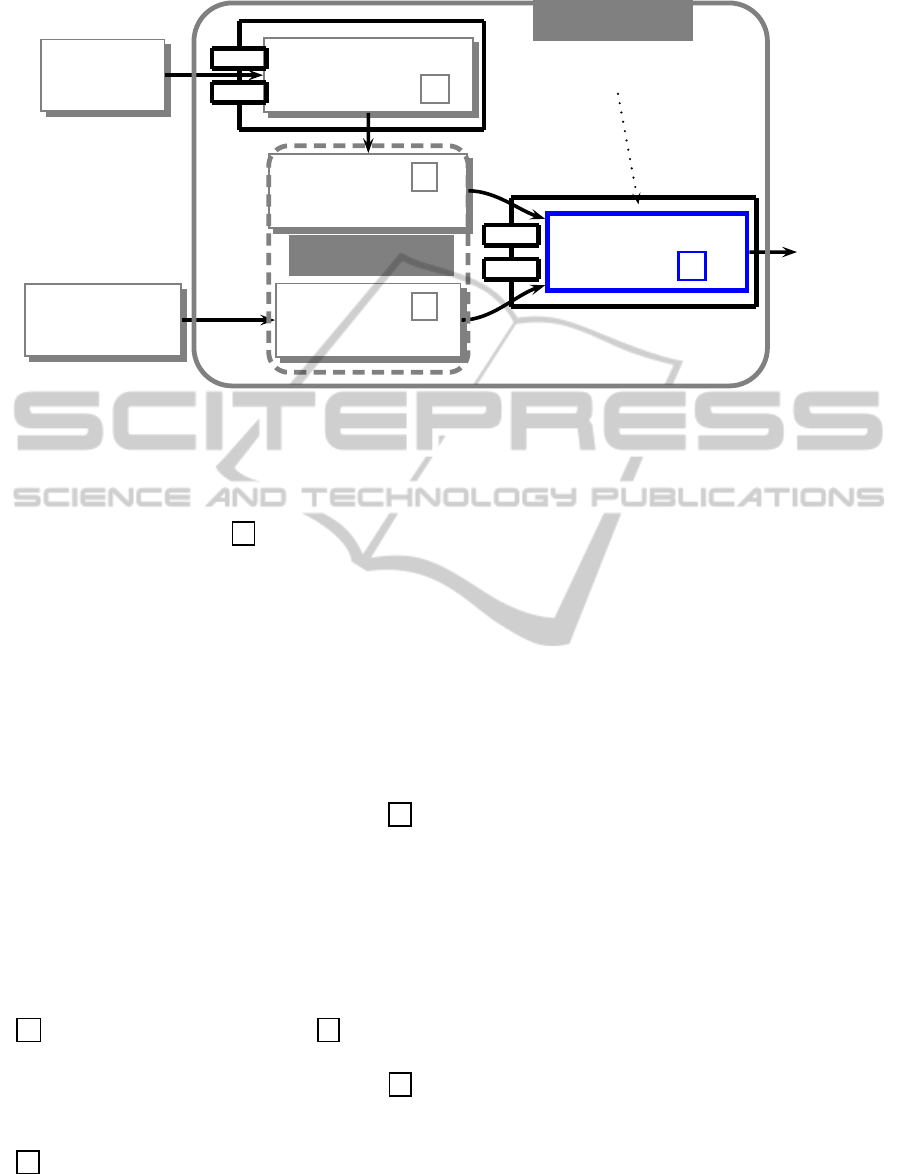
UML
MODEL
TL FORMULAS
GENERATOR G
SYSTEM’S S
SPECIFICATION
SYSTEM’S P
PROPERTIES
TL QUERY
EDITOR
ST TEMPORAL
PROVER
T
p
1
∧ . . . ∧ p
n
⇒ Q
Y/N
REPOSITORY
SYSTEM
Figure 4: Deduction-based verification system.
Such a formula(s) is/are identified by an analyst and
describe(s) the expected properties of the investigated
system. Both the system specification and the exam-
ined properties are input to the T component, i.e. Se-
mantic Tableaux Temporal Prover, or shortly ST Tem-
poral Prover, which enables the automated reasoning
in temporal logic using the semantic tableaux method.
The input for this component is the formula P ⇒ Q,
or, more precisely:
p
1
∧ . . . ∧ p
n
⇒ Q (1)
After the negation of formula 1, it is placed at the
root of the inference tree and decomposed using well-
defined rules of the semantic tableaux method. If the
inference tree is closed, this means that the initial for-
mula 1 is true. Broadly speaking, the output of the
T
component, and therefore also the output of the whole
deductive system, is the answer Yes/No in response to
any introduction of a new tested property for a system
modeled using UML. This output also realizes the fi-
nal step of the procedure shown in Fig. 1.
The whole verification procedure can be summa-
rized as follows:
1. automatic generation of system specification (the
G component), and then stored (the S module)
as a conjunction of all extracted formulas;
2. introduction of a property of the system (the
P
module) as a temporal logic formula or formulas;
3. automatic inference using semantic tableaux (the
T component) for the whole complex formula 1.
Steps 1 to 3, in whole or individually, may be pro-
cessed many times, whenever the specification of the
UML model is changed (step 1) or there is a need for a
new inference due to the revised system specification
(steps 2 or 3).
4 GENERATION OF
SPECIFICATION
Automated support for building any logical specifi-
cation of a modeled system is essential for require-
ments acquisition and formal verification of proper-
ties. Such a specification usually consists of a large
number of temporal logic formulas and its manual
development is practically impossible since this pro-
cess can be monotonous and error-prone. Last but not
least, the creation of such a logical specification can
be difficult for inexperienced analysts. Therefore, all
efforts towards automation of this design phase are
very desirable.
The proposed method and algorithm for an auto-
matic extraction of a logical specification is based on
the assumption that all workflow models for the UML
activity diagrams are built using only well-known de-
sign patterns, c.f. Fig. 2. It should be noted that con-
structed activity workflow models are based on ac-
tivities and actions identified when writing use case
scenarios. The whole process of building a logical
specification involves the following steps:
1. analysis of a workflow model of activities to ex-
tract all design patterns,
2. translation of the extracted patterns to a logical
expression W
L
which is similar to a well-known
regular expression,
3. generation of a logical specification L from the
ENASE2012-7thInternationalConferenceonEvaluationofNovelSoftwareApproachestoSoftwareEngineering
110

logical expression, i.e. receiving a set of formu-
las of linear time temporal logic of class K.
Let us introduce all formal concepts necessary for the
application of the above steps to illustrate the entire
procedure in a more formal way.
The temporal logic alphabet consists of the fol-
lowing symbols: a countable set of atomic formulas
p, q, r, etc., classical logic symbols like true, false, ¬,
∨, ∧, ⇒, ⇔ and two linear temporal logic operators
2 and 3. (One can also introduce other symbols, e.g.
parenthesis, which are omitted here to simplify the
definition.) For this alphabet, syntax rules for build-
ing well-formed logic formulas can be defined. These
rules are based on BNF notation. The definition of
formula of linear time temporal logic LTL includes
the following steps:
• every atomic formula p, q, r, etc. is a formula,
• if p and q are formulas, then ¬p, p ∨ q, p ∧ q,
p ⇒ q, p ⇔ q are formulas, too,
• if p and q are formulas, then 2p, 3p, are formu-
las, too.
Examples of valid, well-formed and typical formulas,
restricted to the logic K, are the following formulas:
p ⇒ 3q and 2¬(p∧ (q∨ r)).
A set of LTL formulas describe temporal prop-
erties of individual design patterns of every UML
activity diagram. This aspect is important as the
approach presented here is based on predefined de-
sign patterns. An elementary set of formulas over
atomic formulas a
i
, where i = 1, . . . , n, which is de-
noted pat(a
i
), is a set of temporal logic formulas
f
1
, ..., f
m
such that all formulas are well-formed (and
restricted to the logic K). For example, an elemen-
tary set pat(a, b, c) = {a ⇒ 3b, 2¬(b ∧ ¬c)} is a
two-element set of LTL formulas, created over three
atomic formulas.
Suppose that there are predefined sets of formulas
for every design pattern of the UML activity work-
flow from Fig. 2. The proposed temporal logic for-
mulas should describe both safety and liveness prop-
erties of each pattern. In this way, Sequence(a, b) =
{a ⇒ 3b, 2¬(a ∧ b)} describes properties of the Se-
quence pattern. Set Concurrency(a, b, c) = {a ⇒
3b∧ 3c, 2¬(a∧ (b∨c))} describes the Concurrency
pattern and Branching(a, b, c) = {a ⇒ (3b ∧ ¬3c) ∨
(¬3b∧ 3c), 2¬(b∧ c)} the Branching pattern.
Let us introduce some aliases for all patterns
(Fig. 2): Seq as Sequence, Concur as Concurrency,
Branch as Branching and Loop as Loop−while.
Every activity diagram workflow is designed us-
ing only predefined design patterns. Every design
pattern has a predefined and countable set of linear
temporal logic formulas. The workflow model can
be quite complex and it may contain nesting patterns.
This is one important reason why it is needed to define
a symbolic notation which represents any potentially
complex structure of the activity workflow. Logical
expression W
L
is a structure created using the follow-
ing rules:
• every elementary set pat(a
i
), where i = 1, . . . , n
and a
i
is an atomic formula, is a logical expres-
sion,
• every pat(A
i
), where i = 1, . . . , n and where A
i
is
either
– a sequence of atomic formulas a
j
, where j =
1, . . . , m, or
– a set pat(a
j
), where j = 1, . . . , m and a
j
is an
atomic formula, or
– a logical expression pat(A
j
), where j =
1, . . . , m
is also a logical expression.
The above defined symbolic notation is equivalent to
a graphical one which is usually the most convenient
for users when modeling a system. However, another
rule describing a special case of a sequence of se-
quences is introduced:
• if pat
1
() and pat
2
() are logical expressions, where
the empty parentheses means any arguments, then
their concatenation pat
1
() · pat
2
(), also noted
pat
1
()pat
2
(), is also a logical expression.
This rule is redundant but the concatenation of se-
quences seems more convenient and in addition it
provides concatenation of sequences as a sequence
of three arguments. Thus, another predefined set
SeqSeq(a, b, c) = {a ⇒ 3b, b ⇒ 3c, 2¬((a ∧ b) ∨
(b∧ c) ∨ (a∧ c))} is introduced. It describes the con-
catenation properties of sequences of two patterns.
Any logical expression represents an arbitrary
complex and nested workflow model for an activ-
ity diagram which was modeled using predefined de-
sign patterns. The logical expression allows repre-
sentation of sets of temporal logic formulas for ev-
ery design pattern. Thus, the last step is to define a
logical specification which is generated from a log-
ical expression. Logical specification L consists of
all formulas derived from a logical expression, i.e.
L(W
L
) = { f
i
: i > 0}, where f
i
is a temporal logic for-
mula. Generating logical specifications, which con-
stitutes a set of formulas, is not a simple summation
of formula collections resulting from a logical expres-
sion. Thus, the sketch of the generation algorithm is
presented below.
The generation process of a logical specification L
has two inputs. The first one is a logical expression
W
L
which is built for the activity workflow model.
ProposaltoImprovetheRequirementsProcessthroughFormalVerificationusingDeductiveApproach
111

The second one is a predefined set P of temporal logic
formulas for every design pattern. Below is an exam-
ple of such a set.
/* version 1.02.2012
/* Activity Design Patterns
Sequence(f1,f2):
f1 => <>f2
[]˜(f1 & f2)
SeqSeq(f1,f2,f3):
f1 => <>f2
f2 => <>f3
[]˜ ((f1 & f2) | (f2 & f3) | (f1 & f3))
Concurrency(f1,f2,f3):
f1 => <>f2 & <>f3
[]˜(f1 & (f2 | f3))
Branching(f1,f2,f3):
f1 => (<>f2 & ˜<>f3) | (˜<>f2 & <>f3)
[]˜(f2 & f3)
Loop-while(f1,f2,f3):
f1 => <>f2
f2 & c(f2) => <>f3
f2 & ˜c(f2) => ˜<>f3
f3 => <>f2
[]˜((f1 & f2) | (f2 & f3) | (f1 & f3))
Most elements of the P set, i.e. comments, two tem-
poral logic operators, classical logic operators, are not
in doubt. f
1
, f
2
etc. are atomic formulas for a pattern.
They constitute a kind of formal arguments for a pat-
tern. 3 f means that sometime (or eventually in the
future) activity f is completed, i.e. the token left the
activity. c( f) means that the logical condition asso-
ciated with activity f has been evaluated and is sat-
isfied. All formulas describe both safety and liveness
properties for a pattern.
The output of the generation algorithm is the logi-
cal specification understood as a set of temporal logic
formulas. The sketch of the algorithm is as follows:
1. At the beginning, the logical specification is
empty, i.e. L =
/
0;
2. The most nested pattern or patterns are processed
first, then, less nested patterns are processed one
by one, i.e. patterns that are located more towards
the outside;
3. If the currently analyzed pattern consists only of
atomic formulas, the logical specification is ex-
tended, by summing sets, by formulas linked to
the type of the analyzed pattern pat(), i.e. L =
L∪ pat();
4. If any argument is a pattern itself, then the logical
disjunction of all its arguments, including nested
arguments, is substituted in place of the pattern.
The above algorithm refers to similar ideas in
work (Klimek, 2012). Let us supplement the algo-
rithm by some examples. The example for the step 3:
SeqSeq(p, q, r), gives L = {a ⇒ 3b, b ⇒ 3c, 2¬((a∧
b) ∨ (b ∧ c) ∨ (a ∧ c))} and Branch(a, b, c) gives L =
{a ⇒ (3b ∧ ¬3c) ∨ (¬3b ∧ 3c), 2¬(b ∧ c)}. The
example for the step 4: Concur(Seq(a, b), c, d) leads
to L = {a ⇒ 3b, 2¬(a ∧ b)} ∪ {(a ∨ b) ⇒ 3c ∧
3d, 2¬((a∨ b) ∧ (c∨ d))}.
Let us consider a simple example to illustrate the
approach. This example illustrates the proposed ver-
ification method only for a single activity diagram
(workflow). This is due to size constraints on the
work. A model consisting of several activity diagrams
obtained from multiple use case scenarios could also
be considered. A single liveness property (3) is veri-
fied but it is possible to verify other properties, includ-
ing the safety property. When any formula describing
activity is considered, e.g. 3 p, this means that the ac-
tivity p is sometime (or eventually in the future) com-
pleted.
Suppose
2
that an owner of the “Theater of the
Absurd”, which has recently declined in popularity,
wants to organize a new and great performance to be-
gin a new and splendid period for the institution. An-
alyzing the scenario of the UML use case “Prepara-
tion of a theatrical performance” the following activ-
ities are identified: “Choose a theater script”, “Buy
a theater script”, “Employ actors”, “Actors rehearse
on stage”, “Design costumes and scenery” “Prepare
costumes”, “Prepare scenery” and “Dress rehearsal”.
The way of creating the use case scenario is not in
doubt and therefore is omitted here. The scenario is
usually given in a tabular form and its steps should in-
clude all the above identified activities. When build-
ing a workflow for the activity diagram, a combina-
tion of Sequence and Concurrency patterns is used.
The logical expression W
L
for this model is
SeqSeq(ChooseScript,Concur(BuyScript,
Seq(EmployActors, ActorsRehearse),
Concur(Design, PrepareCostumes,
PrepareScenery)), DressRehearsal)
or after the substitution of propositions as letters of
the Latin alphabet: a – Choose a theater script, b –
Buy a theater script, c – Employ actors, d – Actors
rehearse on stage, e – Design costumes and scenery,
f – Prepare costumes, g – Prepare scenery, and h –
Dress rehearsal, then logical expression W
L
is
SeqSeq(a,Concur(b, Seq(c, d),Concur(e, f, g)), h)
2
This example is an adaptation of another example from
lectures by Prof. Tomasz Szmuc (AGH University of Sci-
ence and Technology, Krak´ow, Poland).
ENASE2012-7thInternationalConferenceonEvaluationofNovelSoftwareApproachestoSoftwareEngineering
112

From the obtained expression a logical specification
L will be built in the following steps. At the begin-
ning, the specification of a model is L =
/
0. Most
nested patterns are Seq and Concur. Sequence gives
L = L∪ { c ⇒ 3d, 2¬(c∧ d)}, and then Concurrency
gives L = L ∪ {e ⇒ 3 f ∧ 3g, 2¬(e ∧ ( f ∨ g))}. The
next considered pattern is Concurrency for which the
disjunction of arguments is considered L = L∪ {b ⇒
3(c ∨ d) ∧ 3(e ∨ f ∨ g), 2¬(b ∧ ((c ∨ d) ∨ (e ∨ f ∨
g)))}. The most outside situated pattern gives L =
L∪ {a ⇒ 3(b∨ c∨ d ∨ e ∨ f ∨ g), (b∨ c∨ d ∨ e∨ f ∨
g) ⇒ 3h, 2¬((a ∧ (b ∨ c∨ d ∨ e∨ f ∨ g)) ∨ ((b ∨ c ∨
d ∨ e∨ f ∨ g) ∧ h) ∨ (a∧ h))}.
Thus, the resulting specification contains formulas
L = {c ⇒ 3d, 2¬(c∧ d), e ⇒ 3 f ∧ 3g,
2¬(e∧ ( f ∨ g)), b ⇒ 3(c∨ d) ∧ 3(e∨ f ∨ g),
2¬(b∧ ((c∨ d) ∨ (e∨ f ∨ g))),
a ⇒ 3(b ∨ c ∨ d ∨ e∨ f ∨ g),
(b∨ c∨ d ∨ e ∨ f ∨ g) ⇒ 3h,
2¬((a∧ (b∨ c∨ d ∨ e∨ f ∨ g)) ∨
((b∨ c∨ d ∨ e∨ f ∨ g) ∧ h) ∨ (a∧ h))} (2)
The examined property can be
a ⇒ 3h (3)
which means that if the theater script is chosen then
sometime in the future the dress rehearsal is com-
pleted. The whole formula to be analyzed using the
semantic tableaux method is
((c ⇒ 3d) ∧ (2¬(c∧ d)) ∧ (e ⇒ 3 f ∧ 3g) ∧
(2¬(e∧ ( f ∨ g))) ∧
(b ⇒ 3(c∨ d) ∧ 3(e∨ f ∨ g)) ∧
(2¬(b∧ ((c∨ d) ∨ (e∨ f ∨ g)))) ∧
(a ⇒ 3(b∨ c∨ d∨ e∨ f ∨ g)) ∧
((b∨ c∨ d ∨ e∨ f ∨ g) ⇒ 3h) ∧
(2¬((a∧ (b∨ c ∨ d∨ e∨ f ∨ g)) ∨
((b∨ c∨ d ∨ e∨ f ∨ g) ∧ h) ∨ (a∧ h))))
⇒ (a ⇒ 3h) (4)
Formula 2 represents the output of the G compo-
nent in Fig. 4. Formula 4 provides a combined input
for the
T component in Fig. 4. Presentation of a full
reasoning tree for formula 4 exceeds the size of the
work since the tree contains many hundreds of nodes.
The formula is true and the examined property 3 is
satisfied in the considered activity model.
5 CONCLUSIONS
The work presents a new approach to the formal
verification of requirements models using temporal
logic and the semantic tableaux method. The paper
presents the method for transformation of activity di-
agram design patterns to logical expressions which
represent a model of requirements. The algorithm for
generating logical specifications from a logical ex-
pression is proposed. The advantage of the whole
methodology is that it provides an innovative concept
for formal verification which might be done for any
requirements model created using the UML use case
and activity diagrams. It enables both receiving high-
quality requirements and stable software systems as
well as the transformation from verified goal-oriented
requirements to reliable systems.
Future work may include the implementation of
the logical specification generation module and the
temporal logic prover. Another possibility is an exten-
sion of the deduction engine in order to support more
complex logics to compare with the minimal tempo-
ral logic. Important issues are questions how to apply
the approach in the real software developmentprocess
and in the industry practice. The approach should
results in a CASE software providing modeling re-
quirements and software design. The purpose of the
CASE software should include both the identification
of activities and actions in use case scenarios, work-
flow modeling in activity diagrams as well as detect-
ing and resolving possible inconsistencies of models
being designed by different designers. All the above
mentioned efforts will lead to user friendly deduction
based formal verification of requirements engineering
and user centered software development.
ACKNOWLEDGEMENTS
I thank Anonymous Referees for comments and
suggestions for improvement of this work. The
work was supported by the AGH UST internal grant
no. 11.11.120.859.
REFERENCES
Barrett, S., Sinnig, D., Chalin, P., and Butler, G. (2009).
Merging of use case models: Semantic foundations. In
3rd IEEE International Symposium on Theoretical As-
pects of Software Engineering (TASE’09), pages 182–
189.
Cabral, G. and Sampaio, A. (2008). Automated formal
specification generation and refinement from require-
ment documents. Journal of the Brazilian Computer
Society, 14 (1):87–106.
Chellas, B. F. (1980). Modal Logic. Cambridge University
Press.
ProposaltoImprovetheRequirementsProcessthroughFormalVerificationusingDeductiveApproach
113

Clarke, E., Grumberg, O., and Peled, D. (1999). Model
Checking. MIT Press.
Clarke, E., Wing, J., and et al. (1996). Formal methods:
State of the art and future directions. ACM Computing
Surveys, 28 (4):626–643.
Cockburn, A. (2001). Writing Effective Use Cases.
Addison-Wesley.
D’Agostino, M., Gabbay, D. M., H¨ahnle, R., and Posegga,
J. (1999). Handbook of Tableau Methods. Kluwer
Academic Publishers.
Emerson, E. (1990). Handbook of Theoretical Computer
Science, volume B, chapter Temporal and Modal
Logic, pages 995–1072. Elsevier, MIT Press.
Eshuis, R. and Wieringa, R. (2004). Tool support for ver-
ifying uml activity diagrams. IEEE Transactions on
Software Engineering, 30 (7):437–447.
Fowler, M. (2004). UML Distilled. Third Edition. Addison-
Wesley.
H¨ahnle, R. (1998). Tableau-based Theorem Proving. ESS-
LLI Course.
Hurlbut, R. R. (1997). A survey of approaches for describ-
ing and formalizing use cases. Technical Report XPT-
TR-97-03, Expertech, Ltd.
Kazhamiakin, R., Pistore, M., and Roveri, M. (2004). For-
mal verification of requirements using spin: A case
study on web services. In (SEFM 2004) Proceedings
of the Second International Conference on Software
Engineering and Formal Methods, 28–30 September
2004, Beijing, China, pages 406–415.
Klimek, R. (1999). Introduction to temporal logic [in Pol-
ish]. AGH University of Science and Technology
Press.
Klimek, R. (2012). Towards formal and deduction-based
analysis of business models for soa processes. In Fil-
ipe, J. and Fred, A., editors, Proceedings of 4th In-
ternational Conference on Agents and Artificial Intel-
ligence (ICAART 2012), 6-8 February, 2012, Vilam-
oura, Algarve, Portugal, volume 2, pages 325–330.
SciTePress.
Klimek, R. and Szwed, P. (2010). Formal analysis of use
case diagrams. Computer Science, 11:115–131.
Pelletier, F. (1993). Semantic tableau methods for modal
logics that include the b and g axioms. Technical Re-
port Technical Report FS-93-01, AAAI (Association
for the Advancement of Artificial Intelligence).
Pender, T. (2003). UML Bible. John Wiley & Sons.
Rumbaugh, J., Jacobson, I., and Booch, G. (1999). The Uni-
fied Modeling Language Reference Manual. Addison
Wesley.
Van Benthem, J. (1993–95). Handbook of Logic in Artificial
Intelligence and Logic Programming, chapter Tempo-
ral Logic, pages 241–350. 4. Clarendon Press.
Zhao, J. and Duan, Z. (2009). Verification of use case with
petri nets in requirement analysis. In Proceedings of
the International Conference on Computational Sci-
ence and Its Applications: Part II, ICCSA ’09, pages
29–42, Berlin, Heidelberg. Springer-Verlag.
ENASE2012-7thInternationalConferenceonEvaluationofNovelSoftwareApproachestoSoftwareEngineering
114
