
Modelling of a Grasping and Manipulation Controller
Pavel Dzitac and Abdul Md Mazid
School of Engineering and Built Environment, Central Queensland University, Rockhampton, Australia
Keywords: Grasping, Slippage, Grasp Control, Tactile Sensor.
Abstract: This paper presents the development of a robot grasping and manipulation control system, including the
modelling approach for the control functions, and the criteria used for functional module design in order to
achieve the required functionality and allow its integration into the overall control model. This work is an
example of a practical implementation of a robotic grasping and manipulation controller and may be
relevant to researchers looking for an example of a practical controller design “from scratch”.
1 INTRODUCTION
This paper presents the detailed architecture
modelling of a controller for a robotic object
manipulator, as part of a project that aims to develop
reliable and safe object manipulation as its main
attributes. The controller architecture is designed to
use tactile, force, position and vision sensing. It also
makes use of sensor fusion and learning concepts to
improve controller performance through robust
feedback and “intelligent” decisions.
The concept of instinctive control, for the
purpose of fast reactions to unexpected events such
as collisions or unexpected object slippage, is also
included in the controller architecture.
2 LITERATURE REVIEW
Significant amount of work has already been done
by researcher to develop robot control strategies that
would maximise the capability of individual sensing
technologies through their strategic integration.
(Namiki and Ishikawa, 1996), (Allen et al., 1999),
(Boshra and Zhang, 2000), and (Prats et al., 2009)
used sensor fusion strategies to integrate vision and
tactile sensing to improve grasping. Pelossof et al
(2004) used simulation based on SVM (Support
Vector Machine) method to find optimum grasps for
complex shape objects. Khalil and Payeur (2007)
proposed a control strategy specifically aimed at
grasping deformable objects.
A brief description of the proposed control
architecture in this paper was given by Dzitac and
Mazid (2011). This control architecture is presented
here in detail.
3 MODEL DEVELOPMENT
3.1 The Choice of Control Model
The minimum necessary controller functionality is
based on the minimum project requirements which
are as follows:
1. Find an egg cup that matches the colour of
the target egg (chosen by user), and orientate
the egg cup correctly.
2. Find an egg that matches the colour of the
egg cup and place the egg safely in it.
3. Find a metal bushing and a matching shaft,
and insert the shaft into the bushing.
4. Find a thin-walled plastic drink bottle and
move it safely to a location designated by the
user. The amount water in the bottle not
known to the controller.
The first requirement tests the manipulation
dexterity of the controller because the egg cup could
be sitting upside-down.
The second requirement tests the ability to apply
only the absolutely minimum grasping forces to a
rigid but fragile object that will fail catastrophically
if the allowable grasping force is exceeded.
The third requirement tests the ability to orientate
parts correctly and assemble parts with reasonable
199
Dzitac P. and Mazid A..
Modelling of a Grasping and Manipulation Controller.
DOI: 10.5220/0003992801990204
In Proceedings of the 9th International Conference on Informatics in Control, Automation and Robotics (ICINCO-2012), pages 199-204
ISBN: 978-989-8565-22-8
Copyright
c
2012 SCITEPRESS (Science and Technology Publications, Lda.)

dexterity.
The fourth requirement tests the ability to
maintain grasp control of a deformable object
without prior knowledge of object characteristics.
3.2 Robot Capabilities
The robot must be able to locate the target objects
and potential obstacles in the area and therefore the
robot must have the following capabilities:
1. Detect known objects
2. Estimate object location and orientation
3. Estimate object shape
4. Estimate object size
5. Discriminate objects by colour
For reasonable dexterity the robot must also have:
1. Velocity and acceleration control for fingers,
hand and arm
2. Position control for fingers, hand and arm
3. Tactile sensing for sensitive touch detection
4. Grip force control for heavier grasp
5. Object slippage detection
6. Sufficient degrees of freedom
3.3 Manipulation Controller Design
The specified object manipulation capability
requires a controller with several modules, each with
specialized functions to facilitate grasping and
slippage control. The block diagram in Figure 1
shows the controller functional modules and their
interactions.
The sensors selected for robot’s tactile, force,
position and vision capabilities are considered to be
the minimum number of sensors required for
successful grasping and manipulation.
The tactile, force and position sensors output an
analog voltage of 0 to 5VDC, which is proportional
to the sensing range of the respective sensors.
The term “tactile sensor” is used to represent
sensitive force sensors with a small sensing range.
These sensors are used to detect the instant at which
an object is touched and for manipulating small,
fragile objects. The term “force sensors” is used to
represent sensors with a large force sensing range
and lower sensitivity, such as those in the robot arm.
The Sensing Processor module is based on a
combination of mathematical and logic control
models, depending on the specific requirements of
each function. The Sensing Processor is designed:
1. To filter the digitized analog sensor signals
using digital filters.
2. Use sensor fusion to improve sensor feedback
reliability.
3. Convert the sensor feedback into useful
information for other controller modules.
Figure 1: The grasp and manipulation controller.
ICINCO2012-9thInternationalConferenceonInformaticsinControl,AutomationandRobotics
200
In order to achieve confident manipulation, grasping
force control and slip detection it is important to
have quality feedback signals, which translate into
two specific requirements:
1. The grasping hardware must be capable of
controlling the grasping forces with adequate
mechanical resolution and speed.
2. The feedback system must provide accurate
information, in real time, to the relevant
modules that control the grasping hardware.
Sensor fusion acts as a filter to help produce
reliable information. A voting scheme is used. For
example the controller must know the position of the
robot arm, hand and fingers to determine whether
the slippage sensed by the tactile sensors is real.
The Instinctive Controller module was designed to:
1. Bypass the slow, planned control flow to
generate fast, instinct-like reactions.
2. React to touch, collision and sensory overload
3. Request fast, local reaction from the robot
drives.
4. Provide feedback to the Decision-Making
module and the robot safety controller.
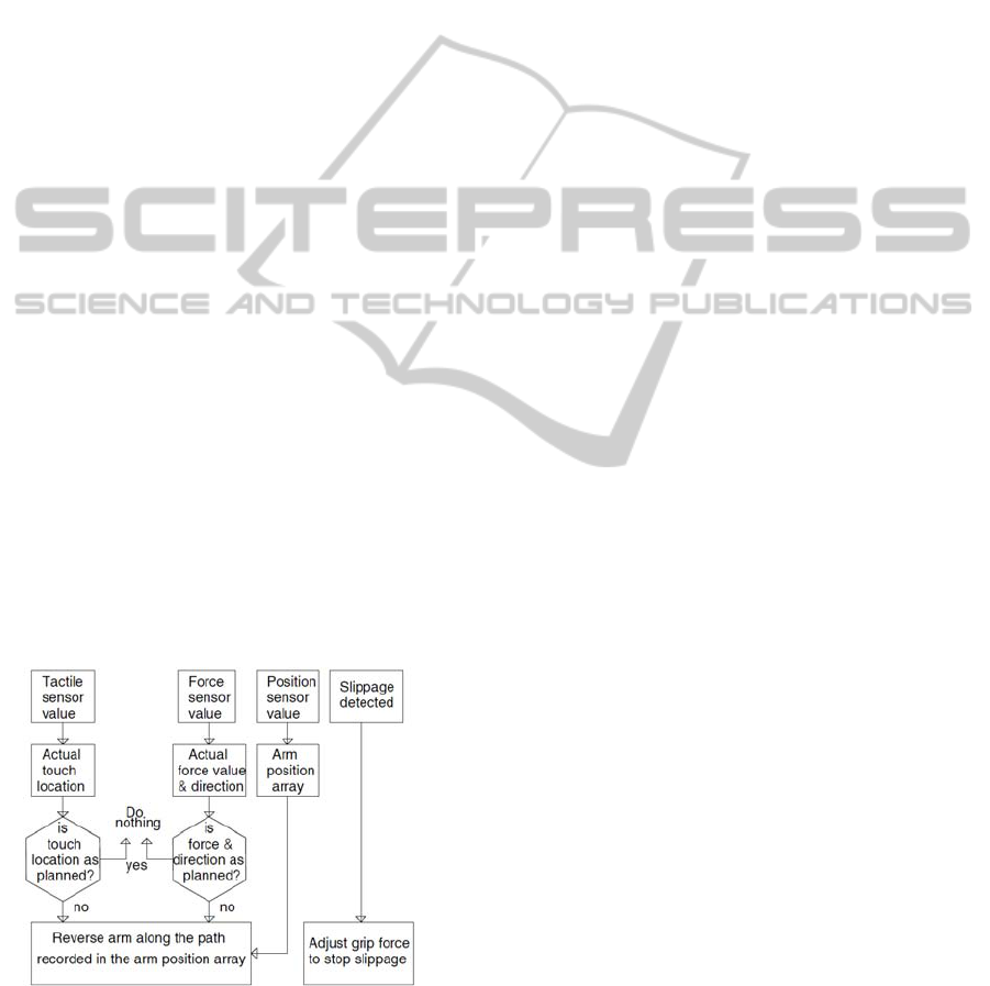
The basic structure of the Instinctive Controller’s
logic decision engine is shown in Figure 2. The
Instinctive Controller is based on logic control that
determines whether the touch and forces sensed by
the robot arm are as planned by the Motion Planning
module or are abnormal. The instinctive motion
controller does not compute a new motion path: it
keeps a record of the current motion path, and in
case of an abnormal event it reverses the robot arm
along the same path for a short distance.
Figure 2: Logic control block diagram of Instinctive
Controller.
In order to prevent loss of control, the Instinctive
Controller reacts fast to slippage events that were
determined by the Sensing Processor and passed to
the Instinctive Controller.
The Decision-Making module was designed to
determine the actions to be taken based on
objectives set by the user, sensory information and
performance feedback from the learning module. It
performs two main tasks: decides whether the object
can be grasped, as shown in Figure 3, and whether
the object can be moved, as shown in Figure 4.
The grasping function uses feedback from the
Sensing Processor that provides information about
the target object and all other objects around the
target object including:
1. Object size
2. Object shape
3. Object location
4. Object orientation
The Decision-Making module monitors the
following information provided by the Sensing
Processor during grasping:
1. Tactile info (touch location/area)
2. Force info (force at finger joints)
3. Arm/hand/finger position info
Before initiating a grasping attempt, the Decision-
Making module searches for obstacles that would
prevent object grasping. An obstacle is any object
located around the target object that prevents
grasping the target object. If grasp is possible it will
forward the following grasp information to the
Motion Planning module:
1. Target object info (size / shape / location /
orientation)
2. Obstacle info (size / shape / location /
orientation)
3. Tactile info
4. Force info
5. Arm / hand / finger position info
This information will be continuously updated
during grasping and forwarded to the Motion
Planning module until grasping is complete. If an
abnormal event takes place, such as an unexpected
collision, the Decision-Making module will abort the
grasping attempt. The grasp abortion criteria are the
same as that used by the Instinctive Controller. The
recovery sequence retracts the robot arm to a safe
position and then tries again.
The Learning function will “remember” which
constraint was violated and why, and will provide
this information to the Decision-Making module
during the next grasping attempt to help prevent the
same estimation error.
ModellingofaGraspingandManipulationController
201

Figure 3: Object grasping algorithm structure.
The object move (relocation) function uses
feedback from the Sensing Processor that provides
the following information during object move:
1. Target object info
2. Tactile info
3. Force at fingers, hand and arm joints
4. Arm/hand/finger position info
5. Object slippage info
The object move function also uses information
compiled by the Decision-Making module which
includes:
1. Local obstacle info
2. Remote location info (where object will be
placed)
3. Remote obstacle info
The Decision-Making module determines whether
there are obstacles that would prevent moving the
object to its new destination. If there is sufficient
distance between the obstacle and the target object
to allow the object to be moved, the Decision-
Making module will decide that the move is possible
and will forward the following object move
information to the Motion Planning module:
1. Target object info
2. Remote location info
3. Local and remote obstacle info
4. Tactile info
5. Force at fingers, hand and arm joints
6. Arm/hand/finger position info
7. Object slippage info
This information will be continuously updated
during object move and forwarded to the Motion
Planning module until object move is complete. If an
abnormal event takes place, such as unexpected
collision, the Decision-Making module will abort the
move attempt. The object move abortion criteria are
the same as that used by the Instinctive Controller.
The recovery sequence retracts the robot arm to a
safe position and then tries again.
Figure 4: Object moving algorithm structure.
The Learning function will “remember” which
constraint was violated and why. It will provide this
information to the Decision-Making module during
the next object move attempt to help prevent the
same estimation error.
The Motion Planning module was designed to
plan the grasping and the motion of the robot arm
based on action requests received from the Decision-
Making module. This module uses rule-based grasp
planning as shown in Figure 5.
Figure 5: Grasp rule for cylindrical objects.
The Planned Motion Controller (planned motion
trajectory generator) was designed to execute the
motion plan generated by the Motion Planning
module. It generates a sequence of motion path
points based on the motion path generated by the
Motion Planning module and velocity constraints,
and feeds these points at the correct time to the robot
drives that perform the actual position control of the
ICINCO2012-9thInternationalConferenceonInformaticsinControl,AutomationandRobotics
202

servo motors.
The Robot hand and arm controller module
consists of the hardware and firmware that executes
robot hand and arm actions, and responds to
instructions received from the motion controllers.
3.4 The Vision System
Figure 6: Simplified block diagram of vision system.
To be capable of finding, grasping and
manipulating objects the robot must be equipped
with a vision system that can perform the vision
tasks mentioned in section 3.1. The vision system is
not the main research objective in this project, but it
is indispensable for an autonomous object grasping
and manipulation system.
At this stage the vision system detects simple
objects, such as cylinders, eggs and drinks bottles,
and estimates their location, orientation and size.
4 IMPLEMENTATION AND
RESULTS
An average egg weighs around 50g (~500mN).
Experimentation shows that to hold an egg in
vertical orientation with a two-finger gripper the
grasping mechanism would have to apply a grasp
force of about 1N. To achieve reasonable force
control during egg grasping the force sensing and
control resolution of the grasping mechanism must
be capable of a minimum resolution of 1 in 100 (i.e.
at least 1N / 100 = 10mN). This is in the sensitivity
range of the tactile force sensors. For this prototype,
the maximum tactile grasping force range of the
grasping mechanism has been limited to 5N.
Assuming that the grasping mechanism has
sufficient mechanical control resolution, the force
sensor signal must be discriminated to 10mN or less.
A 9 bit A/D converter would provide 5N / 511 =
9.8mN, which is sufficient resolution for ideal signal
quality. However the least significant bit (LSB) of
the digitized signal is corrupted by noise, so a better
choice is a 12Bit converter because it provides a
higher signal resolution (5N / 4095 = 1.2mN), which
facilitates noise filtering and signal reconstruction.
The signal reconstruction resolution is dependent
on the A/D converter resolution, sampling frequency
and the number of samples used per sampling
period. The fidelity of the reconstructed signal must
be sufficient to provide a good representation of the
actual sensor signal, minus the random noise.
A digital signal analyser was used to determine
the type of noise in the analog signals coming from
sensors. It was determined that the noise was mostly
random noise.
The Sensing Processor performs digital signal
filtering on the tactile, position and force feedback
signals. The model used for digital filtering is based
on the recursive moving average filter, which is
optimum for eliminating random noise. The filter
used is based on a running average (Smith, 1999) of
20 values and its output y is given by
y[n] = (y [n-1] + x[nm+1] - x[nm - (m-1)]) / 2 (1)
where y[n] is the current point being calculated, y[n-
1] is the previous calculated point, x[nm+1] is the
latest sample, x[nm-(m-1) is the oldest sample, n is
the current sample number and m is the number of
samples in the moving average. Note that y[0] must
be initialise by getting m number of samples and
calculating the average before equation (1) can be
used (Smith, 1999).
The control system uses an FPGA, which is
interfaced with a 12 bit A/D converter that has a
parallel data bus. Each of the 12 bits of the A/D
converter is connected in parallel to the FPGA
inputs, which allows the digital filters to use higher
signal sampling rates if necessary. The 12 bit A/D
provides a resolution of 5V / 4095 = 1.22mV.
The tactile sensor outputs 0-5V when it is
compressed 1mm. The grasping mechanism can
move with a maximum linear velocity of 100mm/s,
ModellingofaGraspingandManipulationController
203

therefore it takes the sensor output 10ms to change
from the minimum of 0V to the maximum of 5V
from the point of contact with the object. The sensor
DC signal is reconstructed at 100ksps samples.
This gives 100ksps * 0.01s = 1000 signal
reconstruction points during the 10ms when the
sensor signal changes from 0 to 5V. This is
equivalent to 5N / 1000 = 5mN tactile grasping force
resolution. Note that during the fastest sensor signal
change rate, the control system can only distinguish
the grasping force at a resolution of 5mN despite the
fact that the A/D converter can provide a resolution
of 1.2mN.
To allow the prototype to manipulate heavier
objects, such as the plastic drink bottle described
earlier, the “bulk” grasping force sensing was
designed for a maximum of 20N.
The same analysis as for the 0-5N range tactile
sensor is applicable to the 0-20N range force sensor.
A 12 bit converter was selected, which provides a
signal conversion resolution of 20N / 4095 = 4.9mN.
The force sensor outputs 0-5V when the finger is
deflected 4mm at the tip (finger has compliant
joints). The grasping mechanism can move with a
maximum linear velocity of 100mm/s, therefore it
takes the sensor output 40ms to change from the
minimum of 0V to the maximum of 5V from the
point of contact with the object. The sensor DC
signal is reconstructed at 100ksps, which gives
100ksps * 0.01s = 1000 signal reconstruction points
during the 40ms when the sensor signal changes
from 0 to 5V. This is equivalent to 20N / 1000 =
20mN grasping force resolution. During the fastest
sensor signal change rate, the control system can
only distinguish the grasping force at a resolution of
20mN despite the fact that the A/D converter can
provide a resolution of 4.9mN.
The position sensors output 0 to 5V per 90
degrees of rotation. Using a 12 bit A/D converter
gives a resolution of 90 deg / 4095 = 0.022 degrees.
If a resolution of 0.03 degrees is used, the resolution
at the end of a robot arm with two links of 300mm
each is 1mm, which is adequate for reliable arm,
hand and finger positioning during object
manipulation.
Object handling experimentation shows that the
choice of sensor signal feedback resolution and
update frequency is adequate for reliable control of
fragile object grasping and safe manipulation.
5 CONCLUSIONS
The main objective in this project is to develop
object grasping and manipulation with collision
detection and slippage control to allow the robot to
manipulate objects safely with useful dexterity. The
most challenging part in the project is to achieve
useful feedback information from sensors.
Currently the experimental tactile slippage
sensing approach is based on a parallel-jaw gripper
that provides acceptable slippage detection but only
in one axis (object rotation in the gripper is only
detected by vision). Further work is needed to
develop a robust slippage sensing strategy that
would provide reliable slippage status feedback to
help detect and prevent slippage in all axes.
Further work is needed to add advanced
functionality to the sensor fusion module. The
learning module also needs further work to improve
its usefulness.
REFERENCES
Namiki, A., Ishikawa, M., 1996, Optimal Grasping using
Visual and Tactile Feedback, Proceedings of the
IEEE/SICS/RSJ International Conference on
Multisensor Fusion and Integration for Intelligent
Systems, Washington DC, USA, December.
Allen, P. K., Miller, A., Oh, P. Y., Leibowitz, B., 1999,
Integration of vision, force and tactile sensing for
grasping, International Journal of Intelligent
Machines, 4(1):129-149.
Boshra, M., Zhang, H., March 2000, Localizing a
polyhedral object in a robot hand by integrating visual
and tactile data, PR(33), No. 3, pp. 483-501.
Pelossof, R., Miller, A., Allen, P., Jebara, T., 2004, An
SVM Learning Approach to Robotic Grasping,
Proceedings of International Conference on Robotics
and Automation (ICRA’04), vol. 4, pp. 3512 -3518.
Khalil, F. F., Payeur, P., 2007, Robotic Interaction with
Deformable Objects under Vision and Tactile
Guidance - a Review, International Workshop on
Robotic and Sensors Environments, pp.1-6, 12-13 Oct.
Prats, M., Sanz, P. J., del Pobil, P. A., May 2009, Vision-
tactile-force integration and robot physical interaction,
Conference on Robotics and Automation, 2009. ICRA
'09. IEEE International, pp.3975-3980.
Dzitac, P., Mazid, M. A., 2011, An Innovative Approach
for Grasping Force Estimation Using Tactile and
Vision Sensors, 15th International Conference on
Mechatronics Technology (ICMT). November 30 to
December 2, Melbourne, Australia.
Smith, S., 1999, The Scientist and Engineer's Guide to
Digital Signal Processing 2nd Ed., California
Technical Publishing, San Diego, California.
ICINCO2012-9thInternationalConferenceonInformaticsinControl,AutomationandRobotics
204
