
Business Processes Modeling through Multi Level Activity Diagrams
Denis Del Villano
1
, Gaetanino Paolone
2
and Paolino Di Felice
1
1
Department of Ingegneria Elettrica e dell'Informazione, University of L'Aquila, L'Aquila, Italy
2
Gruppo SI S.c.a.r.l., Teramo, Italy
Keywords: Business Modeling, UML, Activity Diagrams, Use Case, Correspondence Matrices, Double Tracing.
Abstract: The usage of UML 2.0 activity diagrams at two different levels of abstraction is proposed to consolidate an
already known business modeling approach for the development of large enterprise software applications. In
this way a high continuity between the phases of business modeling and system modeling is obtained.
Moreover, to keep a better control of the completeness of the business modeling artifacts, we recommend to
fill out matrices that make explicit the link among business activities, business use cases and business
objects involved in the automation of the information system.
1 INTRODUCTION
The RUP oriented and Use Case centred
methodology described in (Paolone et al., 2008a;
2008b; 2009; 2010a; 2010b), currently under use
within Gruppo S.I. (www.softwareindustriale.it), is
appropriate for the modeling of enterprise
information systems when the goal is to automate
one of its subsystems. We borrowed such a
modeling and development methodology
to
computerize workflows of a network of banks. The
peculiarity of such a scenario is the existence, within
the enterprise, of the underlying information
system.
This situation makes natural to carry out the
business modeling phase (of subsystems) of the
enterprise in terms of Business UCs
and classes of
Business Objects, as well as the description of the
internal and external information flows.
The everyday experience teaches that, besides
the automation of enterprise subsystems, often it
arises the necessity of:
a) re-engineering (part of) the enterprise
organization before proceeding to its
automation in order, for instance, to either
improve the information flows or to introduce
process innovation;
b) designing from the beginning the information
system of a new enterprise, before proceeding
to its automation.
In both those situations, the just mentioned
methodological approach presents shortcomings due
to the fact that, being UC centred, it is not suitable
for the representation of the processes. The goal of
this paper is to suggest a way to strengthen such a
modeling approach at the business level, so that it
may become applicable with the same effectiveness
also to the mentioned cases “a.” and “b.”.
Today, several notations for describing business
processes are available: BPMN, Petri-nets, BPEL,
UML Activity Diagrams, Data Flow Diagrams, etc.
Among them, a leading position is held by BPMN
(BPMN, 2012) to which, lately, came abreast UML
(e.g., (UML, 2012; Johnston, 2004)).
Research has been done to formally compare the
expressiveness of BPMN Business Process Diagrams
against UML ADs with respect to their suitability to
serve as a business processes modeling formalism
(e.g., (Russel et al., 2006)). The final outcome was
that those notations are basically equivalent.
However, there is an important difference between
them and it concerns the target users of the diagrams.
BPMN Business Process Diagrams are more oriented
to business stakeholders than to system ones, a
category, this latter, equally important when the goal
is to move from business modeling to system
modeling. That’s why, in this paper, we embrace the
choice of UML as the common modeling language
between business and technical stakeholders.
The present paper is organized as follows. Sec.2
recalls the basic elements of the methodology
described in (Paolone et al., 2008a; 2008b; 2009;
2010a; 2010b) in order to provide the reader with the
minimal background necessary to understand the
present proposal. Sec.3 focuses on the proposal.
Basic elements of the contribution concern the
195
Del Villano D., Paolone G. and Di Felice P..
Business Processes Modeling through Multi Level Activity Diagrams.
DOI: 10.5220/0003986201950198
In Proceedings of the 7th International Conference on Evaluation of Novel Approaches to Software Engineering (ENASE-2012), pages 195-198
ISBN: 978-989-8565-13-6
Copyright
c
2012 SCITEPRESS (Science and Technology Publications, Lda.)
adoption of the UML 2.0 ADs to model, at two
different levels of abstraction, the business processes
of the system to be computerized, and what we call
correspondence matrices, offering a global view of
all the underlying business activities, BUCs, BUC
realizations and BOs being part of the artifacts
carried out during the business modeling. Sec.4
touches on an example helpful to instantiate the
ideas sketched in Sec.3.
2 THE BACKGROUND
The final goal of the research described in (Paolone
et al., 2008a; 2008b; 2009; 2010a; 2010b) is to
define a UC
centred methodology, together with a
supporting developing tool, ensuring the continuity
between business modeling, system modeling,
design, and implementation according to the model-
driven paradigm. Their method is structured into
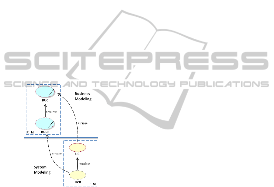
four distinct phases (Fig.1).
Figure 1: A sketch of the four methodological phases.
The first two phases concern business modeling,
while the remaining two concern system modeling.
The business modeling activity starts from the
detection of the organization units involved in the IT
project, then it proceeds to the discovery of their
Business Systems. Inside every BS, we identify
Business UCs and BUC Realizations.
During system analysis, a double trace operation
is accomplished (Fig.1) to map to the system
perspective BUCs and BUCRs, which become the
SUCs and SUCRs, respectively. The logic behind
the trace remains unaltered with respect to the
classical RUP: in the system view, only the UCs that
will be automated will be taken into consideration.
3 THE PROPOSAL
If the business analyst can rely on an existing and
well designed information system, then he has to
analyze the working context and proceed to the
discovery of the BOs and the BUCs. But, if he has to
either design or re-engineer the business (points “a.”
and “b.” of Sec.1.), then he has to proceed
differently. In fact, in those cases, it is necessary to
make use of UML constructs suitable to represent
the information flows, the business processes, and
the relationships existing among them, as well. To
extend the usability of the methodology by Paolone
and his colleagues to those situations, we propose to
model the business processes of the system to be
computerized in terms of UML ADs used at two
different levels of abstraction. Hereinafter, we
discuss such two modeling levels, in sequence.
At the initial stage of the business modeling, by
means of the ADs it is possible to define the
business processes and, hence, the information flows
of the system to be computerized, whether it exists,
or it has to be re-engineered in some of its
subsystems, or it has to be developed from scratch.
Each business process can be modeled in terms of
one or more ADs.
The business modeling of real systems brings to
the construction of manifold artifacts collecting
business activities, BUCs and BOs. As their number
and complexity increase, it becomes difficult to keep
a global view of the project progress. This increases
the risk that the completeness in the identification of
the "elements" composing them cannot be reached.
We managed the complexity by collecting in a
matrix of dimension nxm (hereinafter called
BActivity-BUC correspondence matrix - C1) all the
business activities, BUCs and BOs part of the
artifacts carried out, as soon as they are
accomplished.
Matrix C1 collects the business activities (the
rows) and the BUCs (the columns): to carry out 1
business activity it may require from 1 to m BUCs,
while 1 BUC concurs in the achievement of 1 to n
activities. The generic element of C1 denotes the set
of BOs involved in the BUC
j
in connection with the
BActivity
i
, that is:
C1[BActivity
i
, BUC
j
]={BO
1
, BO
2
,…, BO
k
}.
If BUC
j
is not involved in the BActivity
i
, then
such a set is empty. A BO may be involved in
several BUCs. Fig.2 shows an example.
ENASE2012-7thInternationalConferenceonEvaluationofNovelSoftwareApproachestoSoftwareEngineering
196
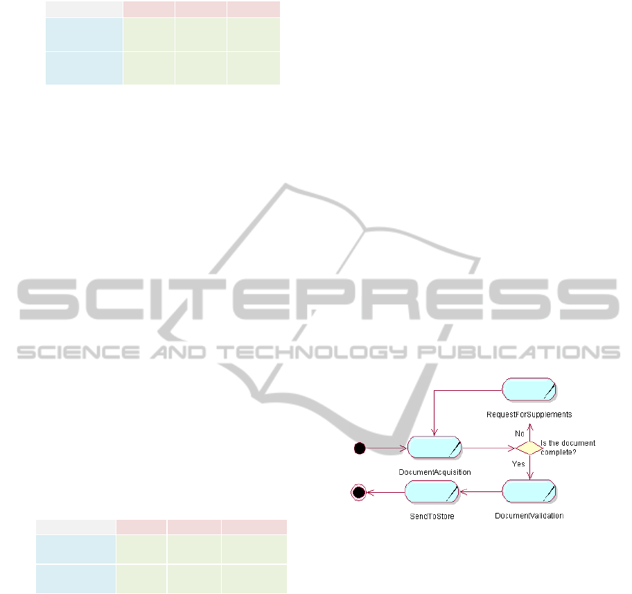
Figure 2: An instance of matrix C1.
Real life projects emphasized the usefulness to
complement the narrative specification of “complex”
BUCs (i.e., those that give rise to at least three
BUCRs) in order to formally detail the logic of the
underlying process in terms of atomic actions. For
each detailed process, it may be necessary up to n
ADs.
For each BUC, we suggest to fill in a DActivity-
BUCR correspondence matrix (C2) - same reasons
as for C1 - (where DActivity stands for Detailed
Activity, that is an activity that denotes elementary
business operations. Examples are given in Sec.4) of
dimension p
xq among the detailed activities (the
rows) and the BUCRs (the columns) that realize the
selected BUC: to carry out 1 detailed activity it may
require from 1 to q BUCRs, while 1 BUCR concurs
in the achievement of 1 to p detailed activities. The
generic element of C2 denotes the set of BOs
involved in the BUCR
j
in connection with the
DActivity
i
, that is:
C2[DActivity
i
, BUCR
j
]={BO
1
, BO
2
,…, BO
h
}.
If BUCR
j
is not involved in the DActivity
i
, then
such a set is empty. A BO may be involved in
several BUCRs. Fig.3 shows an example.
Figure 3: An instance of matrix C2 for a generic BUC.
Matrices C2, referring to an abstraction level
lower than that of C1, may accommodate additional
BOs with respect to those listed in C1. In the
examples of Fig.2 and Fig.3, BO
4
is the extra BO
that arises.
4 A REAL-LIFE EXAMPLE
The business and system modeling approach of
Sec.2, and integrated with ADs (Sec.3), was applied
to the design of a documentary management system
for the BCC of Vomano bank, part of the Central
Institute of Rural and Artisan Banks circuit.
At the initial stage of the business analysis, we
carried out, in close collaboration with the bank top
management, the definition of the corporate
information system. 7 BSs were detected and
analyzed: in the example discussed hereinafter, we
focus on one of them: the BS
DocumentaryManagement. The BCC bank adheres to
the Green Economy vision. To design an
information system oriented to the Green Banking it
is mandatory to adopt a documentary management
system allowing to reset the circulation of paper-
based documents within the bank.
For each identified BS, the pertinent business
processes were enucleated and modeled through
high level of abstraction UML ADs (Sec.3). In this
section, we will refer to the business process
DocumentDematerialization of the
DocumentaryManagement BS. Fig.4 shows the
corresponding AD that describes the logic of such a
business process in terms of a certain number of not-
atomic actions. The
DocumentAcquisition activity,
for instance, denotes the set of atomic actions
needed to file a document in the system.
Figure 4: An AD at a high level of abstraction.
For the 7 BSs of the BCC of Vomano, 22 BUCs
were detected and 15 high level of abstraction ADs
were realized. Fig.5 shows the portion of matrix C1
concerning the 4 business activities of Fig.4 and the
pertinent BUCs. Those BUCs are part of the
business UC model (Johnston, 2004) not shown here
because of space limits. Among the listed BUCs, the
most complex is
DocumentAcquisition realized by
5 BUCRs (Fig.6). The narrative specification of the
DocumentAcquisition BUC was complemented by
4 detailed ADs, each modeling the detailed logic of
the BUC in terms of atomic actions. Two of them
are shown in Fig.7, where, for instance, the
Document’sTemplateSelection represents an
atomic action. Fig.8 shows the portion of C2
regarding the ADs of Fig.7.
C1=
BUC
0
BUC
1
BUC
2
BActivity
0
{BO
1
,
BO
2
}
BActivity
1
{BO
1
,
BO
3
}
{BO
2
,
BO
3
}
C2 =
BUCR
0
BUCR
1
BUCR
2
DActivity
0
{BO
2
}
{BO
2
,
BO
3
}
DActivity
1
{BO
1
,
BO
4
}
BusinessProcessesModelingthroughMultiLevelActivityDiagrams
197
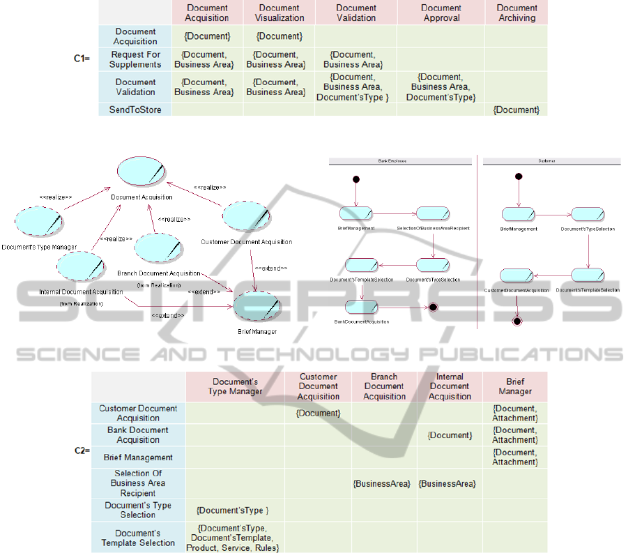
Figure 5: A partial instance of the BActivity-BUC correspondence matrix (C1).
Figure 6: DocumentAcquisition realization diagram.
Figure 7: Two detailed ADs.
Figure 8: A partial instance of the DActivity-BUCR correspondence matrix (C2).
REFERENCES
BPMN, 2012. Business Process Model and Notation,
Version 2.0 (www.bpmn.org/)
Johnston S., 2004. Rational UML Profile for business
modeling. IBM Rational. (www.ibm.com/developer
works/rational/library/)
Kruchten, P., 2003. Rational Unified Process, An
Introduction. Addison-Wesley, 2
nd
edition, UK.
Paolone, G. et al., 2008a. A methodology for building
enterprise Web 2.0 Applications. 10
th
Int. Conf. on the
Modern Information Technology in the Innovation
Processes of the Industrial Enterprises.
Paolone, G. et al., 2008b. Design and Development of web
2.0 Applications. 5
th
Conf. of the Italian Chapter of the
Association for Information Systems.
Paolone, G. et al., 2009a. Web 2.0 Applications: model-
driven tools and design. 6
th
Conf. of the Italian
Chapter of the AISs.
Paolone, G. et al., 2010a. A Business Use Case driven
methodology: a step Forward. 5
th
Int. Conf. on
Evaluation of Novel Approaches to Software
Engineering.
Paolone, G. et al., 2010b. Use case double tracing linking
business modeling to software development. 7
th
Conf.
of the Italian Chapter of the AISs.
Russell, N. et al., 2006. On the suitability of UML 2.0
activity diagrams for business process modeling. 3
rd
Asia-Pacific Conf. on Conceptual Modelling.
Conferences in Research and Practice in Information
Technology, Vol. 53. M. Stumptner, S. Hartmann and
Y. Kiyoki, Eds.
UML, 2012. Unified Modeling Language, Version 2.4.1,
(www.uml.org/)
ENASE2012-7thInternationalConferenceonEvaluationofNovelSoftwareApproachestoSoftwareEngineering
198
