
DEPTH CAMERA TECHNOLOGY COMPARISON
AND PERFORMANCE EVALUATION
Benjamin Langmann, Klaus Hartmann and Otmar Loffeld
ZESS – Center for Sensor Systems, University of Siegen, Paul-Bonatz-Strasse 9-11, Siegen, Germany
Keywords: Depth, Range camera, Time-of-Flight, ToF, Photonic Mixer Device, PMD, Comparison.
Abstract: How good are cheap depth cameras, namely the Microsoft Kinect, compared to state of the art Time-of-
Flight depth cameras? In this paper several depth cameras of different types were put to the test on a variety
of tasks in order to judge their respective performance and to find out their weaknesses. We will concentrate
on the common area of applications for which both types are specified, i.e. near field indoor scenes. The
characteristics and limitations of the different technologies as well as the concrete hardware
implementations are discussed and evaluated with a set of experimental setups. Especially, the noise level
and the axial and angular resolutions are compared. Additionally, refined formulas to generate depth values
based on the raw measurements of the Kinect are presented.
1 INTRODUCTION
Depth or range cameras have been developed for
several years and are available to researchers as well
as on the market for certain applications for about a
decade. PMDTec, Mesa Imaging, 3DV Systems and
Canesta were the companies driving the
development of Time-of-Flight (ToF) depth
cameras. In recent years additional competitors like
Panasonic, Softkinetic or Fotonic announced or
released new models.
The cameras of all these manufactures have in
common that they illuminate the scene with infrared
light and measure the Time-of-Flight. There are two
operation principles: pulsed light and continuous
wave amplitude modulation. The earlier comes with
the problem of measuring very short time intervals
in order to achieve a resolution which corresponds to
a few centimeters in depth (e.g. ZCam of 3DV
Systems). The continuous wave modulation
approach avoids this by measuring the phase shift
between emitted and received modulated light which
directly corresponds to the Time-of-Flight and in
turn to the depth, where ambiguities in form of
multiples of the modulation wavelength may occur.
For a long time the ToF imaging sensors suffered
two major problems: a low resolution and a low
sensitivity resulting in high noise levels.
Additionally, background light caused problems,
when used outdoors. Currently, ToF imaging chips
reaching resolutions up to 200x200 pixels are on the
market and chips with 352x288 pixels are in
development and for a few years some ToF chips
feature methods to suppress ambient light (e.g.
Suppression of Background Illumination - SBI).
Other depth cameras or measuring devices, such
as laser scanners or structured light approaches,
were not able to provide (affordably) high frame
rates for full images with a reasonable resolution and
not e.g. lines. This was true until in 2010 Microsoft
(PrimeSense) released the Kinect. Instead of using a
time varying pattern as was widely applied
previously, it uses a fixed irregular pattern
consisting of a great number of dots produced by an
infrared laser led and a diffractive optical element.
The Kinect determines the disparities between the
emitted light beam and the observed position of the
light dot with a two megapixel grayscale imaging
chip. The identity of a dot is determined by utilizing
the irregular pattern. Here it seems that the depth of
a local group of dots is calculated simultaneously,
but the actual method remains a secret up until
today. Once the identity of a dot is known the
distance to the reflecting object can be easily
triangulated. In addition to the depth measurements,
the Kinect includes a color imaging chip as well as
microphones.
The accuracy and the reliability of such a low
cost consumer product, which is to our knowledge
438
Langmann B., Hartmann K. and Loffeld O. (2012).
DEPTH CAMERA TECHNOLOGY COMPARISON AND PERFORMANCE EVALUATION.
In Proceedings of the 1st International Conference on Pattern Recognition Applications and Methods, pages 438-444
DOI: 10.5220/0003778304380444
Copyright
c
SciTePress
also the first of its kind, is in question and will be
evaluated in the course of this paper. Instead of an
investigation of a specific application, the approach
taken to judge the performance of the Kinect is to
devise a set of experimental setups and to compare
the results of the Kinect to state of the art ToF depth
cameras.
This paper is structured as follows: In section 2
the related literature is reviewed and in section 3 an
overview of the depth cameras used in the
comparison is given. In section 4 the experimental
setups are detailed and the results are discussed. This
paper ends with a conclusion in section 5.
2 RELATED WORK
The performance of ToF cameras using the Photonic
Mixer Divece (PMD) was widely studied in the past.
Noteworthy are for example (Rapp et al., 2008) and
(Chiabrando et al., 2009). The measurement quality
at different distances and using different exposure
times is evaluated. Lottner et al. discuss the
influence and the operation of unusual lighting
geometries in (Lottner et. al., 2008), i.e. lighting
devices not positioned symmetrically around the
camera in close distance.
In (Wiedemann et al., 2008) depth cameras from
several manufactures are compared, which are
PMDTec, Mesa Imaging and Canesta. The
application considered is 3D reconstruction for
mobile robots. And in (Beder et al., 2007) PMD
cameras are compared to a stereo setup. They use
the task of scene reconstruction to judge the
performance of both alternatives.
The most closely related paper is (Stoyanov et
al., 2011), in which two ToF cameras are compared
to the Kinect and to a laser scanner. The application
in mind is navigation for mobile robots and the
methodology is the reconstruction of a 3D scene
with known ground truth.
3 EVALUATED DEPTH
CAMERAS
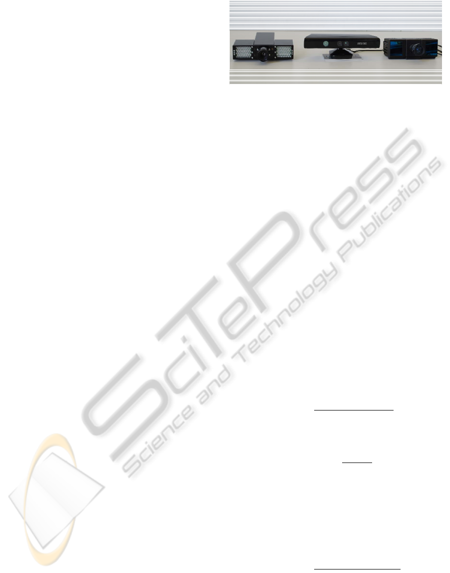
The comparison involves three different depth
cameras which are shown in figure 1. The Microsoft
Kinect as a recent consumer depth camera in
addition to two Time-of-Flight cameras based on the
Photonic-Mixer-Device (PMD), all of which will be
briefly discussed in the following.
Figure 1: Depth cameras used in the evaluation. Left
PMDTec 3k-S, middle Microsoft Kinect and on the right
PMDTec CamCube 41k.
3.1 Microsoft Kinect
The Microsoft Kinect camera uses a diffractive
optical element and an infrared laser diode to
generate an irregular pattern of dots (actually, the
same pattern is repeated 3x3 times). It incorporates a
color and a two megapixel grayscale chip with an IR
filter, which is used to determine the disparities
between the emitted light dots and their observed
position. In order to triangulate the depth of an
object in the scene the identity of an observed dot on
the object must be known. With the irregular pattern
this can be performed with much more certainty than
with a uniform pattern. The camera uses a 6mm lens
and produces a 640x480 pixel sized raw depth map
which consists of an 11-bit integer value per pixel.
The depth values describe the distance to the
imaginary image plane and not to the focal point.
There are currently two formulas to calculate the
depth in meters publicly known, cf. (OpenKinect
Wiki). An integer raw depth value d is mapped to a
depth value in meters with a simple formula by
=
1
−0.00307 +3.33
.
(1)
A more precise method is said to be given by
d
= 0.1236 ∙
d
2842.5
+1.186.
(2)
Since the depth map has about 300k pixels,
calculating the later formula 30 times per second can
be challenging or even impossible especially for
embedded systems.
Using the translation unit described in section 4.3
refined formulas have been determined:
=
1
−0.8965∙ +3.123
(3)
d
= 0.181
0.161d+4.15
.
(4)
See section 4.3 for a comparison of these formulas.
DEPTH CAMERA TECHNOLOGY COMPARISON AND PERFORMANCE EVALUATION
439
3.2 PMDTec CamCube 41k
The CamCube 41k by PMDTec[Vision], cf.
(PMDTechnologies GmbH), contains a 200x200
pixel PMD chip and includes two lighting units.
Modulated infrared light with frequencies up to
21MHz is emitted and the phase shift between the
emitted and received light is calculated. The phase
corresponds to the distance of the reflecting object
and it is determined using the so-called four phase
algorithm. It operates by recording four images A
1
to
A
4
at different phase offsets and then using the arc
tangent relationship to retrieve the phase difference
by
=arctan
A
−A
A
−A
.
(5)
With this phase difference the distance can be
determined with
=
c∙φ
2π∙
f
,
(6)
where c ist the speed of light and f is the modulation
frequency.
The CamCube uses a method to suppress
background illumination called SBI to allow for
outdoor imaging. It provides the possibility to
synchronize the acquisition of images with the
means of a hardware trigger. A wide variety of
different lenses can be used due to the standard CS-
mount adapter. The camera is connected to a
computer via USB.
3.3 PMDTec 3k-S
The 3k-S PMD camera is a development and
research version of PMDTec and it uses an older
PMD chip with only 64x48 pixels. It features a SBI
system and contains a C-mount lens adapter and
uses firewire (IEEE-1394) to communicate with the
computer. This PMD camera is known to be
significantly less sensitive than cameras with newer
PMD chips even though the pixel pitch is 100nm
compared to 45nm of the 41k PMD chip.
4 EXPERIMENTAL SETUPS
In this section the evaluation methods and the most
notable results of the comparison will be discussed.
For the first experiments only the CamCube will be
used as a reference for the Kinect, due to space
restrictions. To make the results comparable an
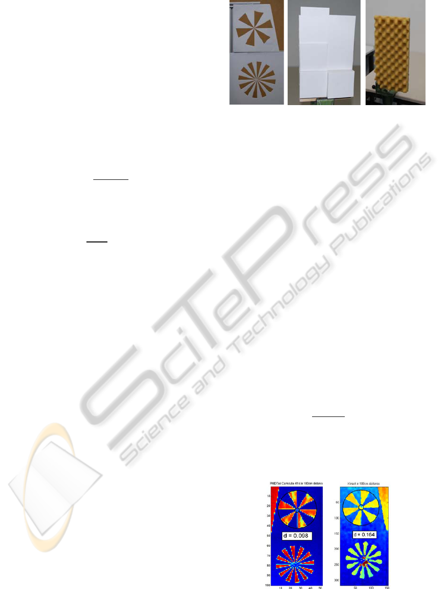
Figure 2: Resolution test objects. Left: two Böhler Stars
with 20cm diameter each. Middle and right: two objects to
evaluate and visualize the angular and axial resolution of
depth cameras.
appropriate lens has to be chosen for the CamCube. Since
the Kinect uses a fixed 6mm lens and the grayscale chip
has a resolution of 1280x1024 (only 640x480 depth pixels
are transmitted) with a pixel pitch of 5.2µm this results in
a chip size of 6.66x5.33mm. The CamCube has a
resolution of 200x200 pixels with a pixel pitch of 45µm
resulting in a chip size of 9x9mm. Therefore, the
corresponding lens for the Cambube would have focal
length of 8.11mm for the width and about 10.13mm for the
height. Due to obvious limitations a lens with a focal
length of 8.5mm was chosen as a compromise.
4.1 Böhler-Star
A Böhler Star, see figure 2, is a tool to determine the
angular or lateral resolution of depth measurement
devices. It can be understood as a three dimensional
Siemens-Star. In (Böhler et al., 2003) it was used to
compare laser scanners. But especially for the
Kinect, for which the effective resolution is not
known, it promises insights. The axial resolution r of
an imaging device can be calculated as
=
π∙d∙M
n
(7)
with n being the number of fields of the star (here 12
and 24 respectively), d being the ratio of the
diameter of the incorrectly measured circle in the
middle of the star to the diameter M of the star.
(a) CamCube (b) Kinect
Figure 3: Results for the Böhler Stars at 1 meter distance.
ICPRAM 2012 - International Conference on Pattern Recognition Applications and Methods
440
For the Böhler Stars frames were taken at different
distances and in figure 3 the respective parts of one
set of the resulting images are shown. In theory the
CamCube with a 8.5mm lens has an opening angle
of 55.8 degrees which leads to an angular resolution
of 0.28 degrees. Using the Böhler stars in one meter
distance the angular resolution of the CamCube can
be specified with 0.51cm, which corresponds to 0.29
degrees. Therefore, the theoretical value can be
considered to be confirmed.
The Kinect has an opening angle of 58.1 degrees
and with 640 pixels in width it has a theoretical
angular resolution of 0.09 degrees (0.12° in height).
In practice an angular resolution of 0.85cm and 0.49
degrees was determined. This corresponds to a
resolution of 118 pixels in width. The significant
difference is due to the fact, that multiple pixels are
needed to generate one depth value (by locating the
infrared dot). Although the Kinect contains a two
megapixel chip and delivers only a VGA depth map,
this still does not to compensate the need for
multiple pixels. Additionally, the Kinect performs to
our knowledge either a post-processing or it utilizes
regions in the identification process, which may lead
to errors at boundaries of objects.
This observation agrees with estimates that the
dot pattern consists of about 220x170 dots which can
be understood as the theoretical limit of the lateral
resolution.
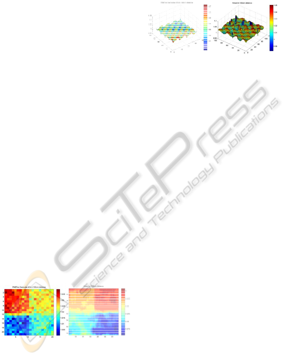
4.2 Depth Resolution Test Objects
Figure 2 additionally shows two objects to visualize
the angular and axial resolution the depth cameras
shown. The first object consists of a ground plane
and three 6cm x 6cm cuboids of different heights
which are 3, 9 and 1mm. The second object has a
surface close to a sinusoidal formed plane with an
amplitude of 1.75cm and a wave length of 3.5cm.
(a) CamCube 100 cm (b) Kinect 100 cm
Figure 4: Cuboids of different heights recorded using the
Kinect and the Camcube. 10 frames were averaged for
each distance.
(a) CamCube 100 cm (b) Kinect 100 cm
Figure 5: Sinusoidal structure measured with both cameras
in 1 meter distance.
Additionally, a 2x2cm white plane mounted with
a 0.5mm steel wire was placed in some distance to a
wall. Then the depth cameras were positioned at
different distances to the plane and it was checked,
whether they were able to distinguish between the
plane and the wall.
In figure 4 some results for the cuboids are
shown. Here 10 images were averaged. Both
cameras are able to measure the different distances
with high accuracy in one meter distance. At 1.5
meters distance the precision decreases and at 2
meters both cameras cannot resolve the pattern
reliably. And in figure 5 a rendering of the
sinusoidal structure is given. Again both cameras are
able to capture the pattern correctly, but the detail
preservation of the Kinect is higher.
For the small plane we get surprising results. Using
the CamCube the 2x2cm plane stays visible with
correct depth value even in 4.5m distance. The
projection of the plane has then only a size of 0.7
pixels, which is enough to make a measurement. The
pixel will observe a mixture of signals with different
phases, but the one coming from the small plane is
the strongest and therefore the measurement will
function correctly. The Kinect displays a completely
different behavior. Here a second camera with an
optical IR filter was used to observe the infrared dots
on the plane. In 1.75 meters distance the small plane
is invisible to the Kinect. The number of dots on the
plane is less than five. In 1.5 meter distance the
plane is visible at about 50% of the time depending
on the lateral position. In one meter distance the
plane is visible and correctly measure all the time
with about 10-20 dots on the plane. The explanation
for this behavior is the same as for the Böhler stars.
4.3 Translation Unit
All cameras were mounted on a translation unit
which is able to position the cameras at distances
between 50cm and 5 meters to a wall with a
positioning accuracy better than 1mm. The cameras
DEPTH CAMERA TECHNOLOGY COMPARISON AND PERFORMANCE EVALUATION
441
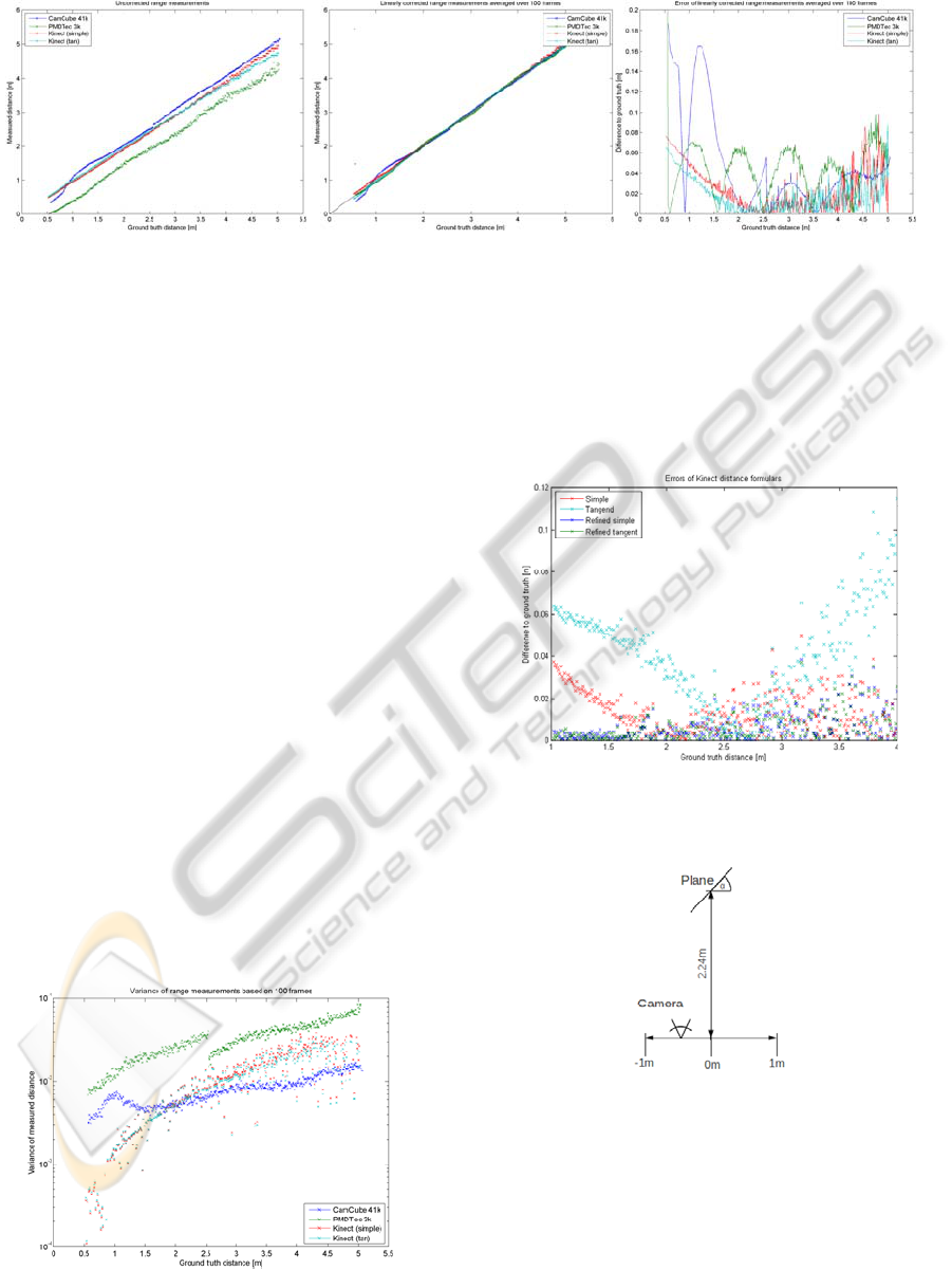
Figure 6: Depth measurements performed with the different cameras. From left to right: raw depth values, linearly corrected
measurements averaged over 100 frames and absolute error to the ground truth distance.
were leveled and were looking orthogonally at the
wall. 100 images were taken per position with a step
size of 1cm which results in 45000 images per
camera. For all ToF cameras the same lens, the same
modulation frequency of 20MHz as well as the same
exposure times (5ms for distances lower that 2.5
meters and 10ms for higher distances) were used.
In figure 6 for the three evaluated cameras the
raw depth measurements, depth values compensated
for constant and linear errors and the absolute error
to the ground truth are shown. Here the CamCube
shows measurement errors for small distances due to
overexposure and both PMD based ToF cameras
show the well known wobbling behavior, cf
(Kahlmann et al., 2006). The distance error of all
cameras is comparable in the optimal region of
application (2-4m) with a slight advantage for the
Kinect. For PMD based cameras more complex
calibration methods exist, see (Lindner and Kolb,
2006) or (Schiller et al., 2008), which are able to
reduce the distance error further. The variance of the
distance measurements based on 100 frames is
plotted in figure 7. Here the Kinect shows
surprisingly higher noise levels than the CamCube
for distances larger than two meters. The variance of
the PMDTec 3k camera is higher due to its limited
lighting system and its low sensitivity.
Figure 7: Variance of the measurements based on 100
recorded images.
In figure 8 the absolute distance errors for the
Kinect are displayed using the different depth
formulas in section 3.1. Again 100 frames were
averaged and constant errors were neglected. The
refined distance formulas perform significantly
better.
Figure 8: Comparison of the different depth formulas for
the Kinect. Displayed is the absolute error neglecting
constant offsets.
Figure 9: Setup to test the ability of depth cameras to
measure plane objects with different angles and positions
relative to a camera path.
4.4 Angular Dependency of
Measurements
Since the measurements of the Kinect are based on
triangulation, it is questionable under which angles
objects can be measured accurately. To evaluate this
ICPRAM 2012 - International Conference on Pattern Recognition Applications and Methods
442
property the camera is moved horizontally and a
plane with a fixed distance to the camera path is
Angles from -40 to -110 degrees and from 40 to 110
degrees with a step size of 5 degrees are applied and
the camera is positioned with offsets from -1 to 1
meter using a step size of 10cm. High accuracy
positioning and rotation devices are used for this
purpose. This leads to a total number of 30x21
images. For each image the measurement quality is
judged and grades are assigned: All pixels valid,
more than 80% valid, more than 20% valid and less
than 20% valid.
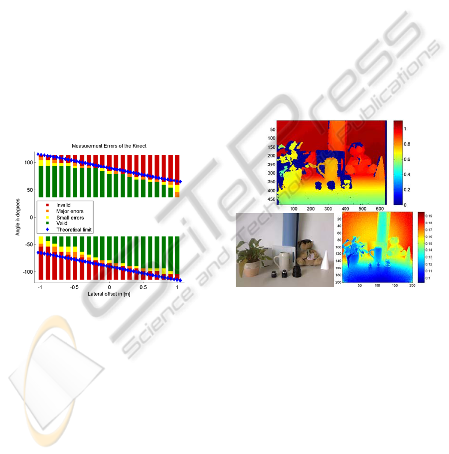
In figure 10 the results for the test setup to
identify difficulties in measuring sharp angles are
shown. We encounter measuring errors for angles up
to 20 degrees less than the theoretical limit, which is
the angle under which the front side of the plane is
invisible. Noteworthy is that the left side of the
depth map displays significant higher sensibility.
This is where the grayscale camera is located and
therefore, the incident light on the plane has here a
sharper angle than on the right side.
Figure 10: Results for the angular measuring setup using
the Kinect.
4.5 Limitations
During the evaluation and in previous experiments
the different types of cameras displayed different
weaknesses. The Kinect showed problems with dull
(LCD monitors) or shiny surfaces or surfaces under
a sharp viewing angle. Obviously, the mounting is
relatively difficult and its lens is not exchangeable,
which limits its application. Different lenses in
combination with different diffractive optical
elements might for example allow for larger
distances. These drawbacks might be solved in
different hardware implementations, but the largest
problems are caused by a systematic limitation. A
significant part of a typical depth map contains no
measurements due to shading: parts of the objects
seen by the grayscale camera are not illuminated by
the IR light beam. Depending on the application
these areas can cause huge problems. In figure 11 a
challenging test scene is shown. Here dark blue in
the depth map for the Kinect indicates invalid
measurements.
Daylight is another source of problems. Since the
grayscale chip of the Kinect uses an optical filter
only infrared light disturbs the measurements.
Therefore, a high power infrared led with a peak
wavelength at 850nm and an infrared diode with
corresponding characteristics have been utilized to
give an impression at which levels of infrared
ambient light the Kinect can be used. It has been
determined that measuring errors occur for an
irradiance of 6-7W/m
2
depending on the distance.
For comparison: sunlight at sea level has an
irradiance of about 75W/m
2
for wavelengths between
800 and 900nm.
Figure 11: difficult test scene. Top depth map generated
with the Kinect (dark blue: invalid), lower left color image
and lower right scene acquired with the CamCube.
The limitations of PMD based ToF cameras are
mainly motion artifacts, which occur when objects
move significantly during the acquisition of the four
phase images. Another problem are mixed phases,
which are produced when a pixel observes
modulated light with different phase shifts due to
reflections or borders of objects inside a pixel.
Additionally, the low resolution and the higher
power requirements limit the application of ToF
cameras to some degree.
5 CONCLUSIONS
In this paper a consumer depth camera, the
DEPTH CAMERA TECHNOLOGY COMPARISON AND PERFORMANCE EVALUATION
443

Microsoft Kinect, which uses a novel depth imaging
technique, is compared to state of the art continuous
wave amplitude modulation Time-of-Flight cameras.
A set of experimental setups was devised to evaluate
the respective strengths and weaknesses of the
cameras as well as of the underlying technology.
It was found that the new technique as well as
the concrete implementation poses a strong
competition in at least the near field indoor area of
application. Only the problems caused by the
triangulation, namely shading due to different
viewpoints, measuring difficulties of sharp angles
and measuring of small structures, are major
weaknesses of the Kinect.
Acquiring full frame depth measurements at high
frame rates in an outdoor environment or for longer
distances seem to be domain of ToF based depth
measuring up until today. For indoor scenes higher
resolutions like the currently developed 100k PMD
chip by PMDTec may level the playing field again.
ACKNOWLEDGEMENTS
This work was funded by the German Research
Foundation (DFG) as part of the research training
group GRK 1564 ’Imaging New Modalities’.
REFERENCES
Beder, C., Bartczak, B., and Koch, R., 2007. A
Comparison of PMD-Cameras and Stereo-Vision for
the Task of Surface Reconstruction using Patchlets. In
Proceedings of the IEEE Conference on Computer
Vision and Pattern Recognition, Minneapolis, USA.
Böhler, W., Bordas Vicent, M., and Marbs, A., 2003.
Investigating Laser Scanner Accuracy. In The
International Archives of Photogrammetry, Remote
Sensing and Spatial Information Sciences, Vol.
XXXIV, Part 5/C15, pp. 696-701.
Chiabrando, F., Chiabrando, R., Piatti, D., and Rinaudo,
F., 2009. Sensors for 3D Imaging: Metric Evaluation
and Calibration of a CCD/CMOS Time-of-Flight
Camera. In Sensors 2009, vol. 9, no. 12, pp. 10080-
10096.
Kahlmann, T., Remondino, F., and Ingensand, H., 2006.
Calibration for increased accuracy of the range
imaging camera swissranger. In International Archives
of Photogrammetry, Remote Sensing and Spatial
Information Sciences, ISPRS Commission V
Symposium, volume XXXVI, pp. 136–141.
Lindner, M., and Kolb, A., 2006. Lateral and Depth
Calibration of PMD-Distance Sensors. In Advances in
Visual Computing, Vol. 2, Springer, pp. 524-533.
Lottner, O., Weihs, W., and Hartmann, K., 2008. Time-of-
flight cameras with multiple distributed illumination
units. In Proceedings of the 8th conference on Signal
processing, computational geometry and artificial
vision, Rhodes, Greece, pp. 40-45.
Möller, T., Kraft, H., Frey, J., Albrecht, M., and Lange,
R., 2005. Robust 3D Measurement with PMD Sensors.
In Proceedings of the 1st Range Imaging Research
Day at ETH Zürich.
OpenKinect Wiki. http://openkinect.org.
PMDTechnologies GmbH. http://www.pmdtec.com.
Radmer, J., Fuste, P. M., Schmidt, H., and Kruger, J.,
2008. Incident light related distance error study and
calibration of the PMD-range imaging camera. In
Proceedings of the IEEE Conference Computer Vision
and Pattern Recognition Workshops, Anchorage,
USA.
Rapp, H., Frank, M., Hamprecht, F. A., and Jahne, B.,
2008. A theoretical and experimental investigation of
the systematic errors and statistical uncertainties of
Time-Of-Flight-cameras. In International Journal of
Intelligent Systems Technologies and Applications,
Vol. 5, No.3/4, pp. 402-413.
Reynolds, M., Doboš, J., Peel, L., Weyrich, T., and
Brostow, G. J., 2011. Capturing Time-of-Flight Data
with Confidence. In Proceedings of the IEEE
Computer Vision and Pattern Recognition Conference,
Colorado Springs, USA.
Schiller, I., Beder, C., and Koch, R. 2008., Calibration of a
PMD-Camera using a Planar Calibration Pattern
together with a Multi-Camera Setup. In The
International Archives of the Photogrammetry,
Remote Sensing and Spatial Information Sciences,
Vol. XXXVII, Part B3a, Beijing, China, pp. 297-302.
Stoyanov, T., Louloudi, A., Andreasson, H., and
Lilienthal, A. J., 2011. Comparative Evaluation of
Range Sensor Accuracy in Indoor Environments. In
Proceedings of the European Conference on Mobile
Robots (ECMR).
Wiedemann, M., Sauer, M., Driewer, F., and Schilling, K.,
2008. Analysis and characterization of the PMD
camera for application in mobile robotics. In
Proceedings of the 17th World Congress of The
International Federation of Automatic Control, Seoul,
Korea, pp. 13689 - 13694.
ICPRAM 2012 - International Conference on Pattern Recognition Applications and Methods
444
