
TOWARDS FORMAL AND DEDUCTION-BASED ANALYSIS
OF BUSINESS MODELS FOR SOA PROCESSES
Radosław Klimek
AGH University of Science and Technology, al. A. Mickiewicza 30, 30-059 Krakow, Poland
Keywords:
Business models, BPMN, SOA and software agents, Formal verification, Deductive reasoning, Semantic
tableaux, Temporal logic, Workflow design patterns, Generating specifications.
Abstract:
The paper concerns formal analysis and verification of business models expressed in BPMN as a visualization
of SOA processes. This verification is based on deductive reasoning which is in a certain kind of opposition
to the well-known approaches based on state exploration (model checking). Semantic tableaux are proposed
as a method of inference. Both the logical specification and the desired system properties are expressed in
the smallest linear temporal logic. Automatic transformations of business models (expressed as workflow
patterns) to temporal logic formulas are proposed. These formulas constitute a logical specification of the
analyzed model. An algorithm for generation of a logical specification is presented.
1 INTRODUCTION
Business modeling is becoming increasingly impor-
tant because it gives anunderstandingof current activ-
ities and the potential for their improvement. BPMN
(Business Process Modeling Notation) is the most
recognized notation for business modeling and might
also be treated as an additional layer providing graph-
ical description of processes which are implemented
in BPEL (Business Process Execution Languages),
which in turn enables execution of the SOA (Ser-
vice Oriented Architecture) software agents on the
workflow engines. There is a possibility of effective
translation from BPMN to BPEL, e.g. (Ouyang et al.,
2006).
Formal reasoning about a system plays a key role
during its developmentbecause it enables reliable ver-
ification of desired properties. There are two ap-
proaches to formal verification of information sys-
tems (Clarke et al., 1996). The first one is based
on state exploration, and the second one on deduc-
tive inference. Both are well-established; however,
during recent years there was a particularly signifi-
cant progress in the field of state exploration which
is called model checking. Unfortunately, the infer-
ence method is now far behind by state exploration
and it seems that there are two reasons for this situ-
ation. The first is a problem of choosing a deductive
system itself. The second and more important prob-
lem is the lack of a method for obtaining the system
specification as a set of temporal logic formulas, and
in particular, the automation of this process.
The main motivation for this work is the lack of
satisfactory and documented results of practical ap-
plication of deductive methods for formal verification
of systems and most of all business models. Another
motivation that follows is the lack of tools for auto-
matic extraction of the logical specification of a sys-
tem, i.e. as a set of temporal logic formulas.
The main contribution of this work is a com-
plete deduction-based system, including its architec-
ture, which allows for automated and formal verifi-
cation of business models. Another contribution is
the use of a non-standard method of deduction for
BPMN business models. Deduction is performed us-
ing the semantic tableaux method for temporal logic.
The automation of the logical specification generation
process is also an important contribution. Theoreti-
cal possibilities of such an automation are discussed.
The generation algorithm for selected design patterns
is presented.
2 PRELIMINARIES
This work is concerned with issues of business mod-
eling for SOA agents, design patterns, temporal logic
and reasoning using semantic tableaux. These issues
will be presented very briefly since details can be
found in many works.
325
Klimek R..
TOWARDS FORMAL AND DEDUCTION-BASED ANALYSIS OF BUSINESS MODELS FOR SOA PROCESSES.
DOI: 10.5220/0003740503250330
In Proceedings of the 4th International Conference on Agents and Artificial Intelligence (ICAART-2012), pages 325-330
ISBN: 978-989-8425-96-6
Copyright
c
2012 SCITEPRESS (Science and Technology Publications, Lda.)

2.1 Business Processes and Patterns
Business processes are collections of structured ac-
tivities which allow for understanding of plans. They
are usually visualized with a flowchart of activities
which are work (or services) that must be performed
in a business model. The most popular business pro-
cesses notation is BPMN, Business Process Modeling
Notation, which was developed by the Business Pro-
cess Management Initiative (BPMI) as a standard for
business process modeling. The main requirement for
BPMN was the simplicity of business model creation.
BPMN notation consists of the following categories
of elements: flow objects, connecting objects, swim-
lanes, artifacts. Detailed information on BPMN ex-
ceeds the size of this work and can be found in many
works, e.g. (OMG, 2009).
The business modeling is related to the concept of
patterns which play an important role in the model-
ing of business processes. A pattern is “the abstrac-
tion form a concrete form which keeps reoccurring
in specific nonarbitrary contexts” (Riehle D., 1996).
Patterns are cataloged and documented in the 23 ob-
jects (der Aalst et al., 2003) which consist of the
following groups: Basic Control, Advanced Branch-
ing, Structural, Multiple Instances, State Based, and
Cancellation. Further considerations in this work
are limited to the five basic control patterns: Se-
quence, Parallel-Split, Synchronization, Exclusive-
Choice and Simple-Merge. In the latter part of the
paper, transformations of these patterns to the logic
formulas which constitute a logical specification of a
business model and which are processed using the se-
mantic tableaux methodology are introduced.
2.2 Logical Background
The logical framework for the presented approach are
temporal logic and reasoning using the method of
semantic tableaux. Temporal logic is a convenient
formalism for specification and verification of se-
quences of events without a strict timing, e.g. (Emer-
son, 1990). Temporal logic formulas can easily ex-
press liveliness and safety properties which play a key
role in proving the properties of a system. Considera-
tions in this paper are limited to axiomatic and deduc-
tive system for the smallest temporal logic, e.g. (Ben-
them, 95). This logic is also known as temporal logic
of the class K, and can be developed and expanded
through the introduction of more complex properties
of the time structure.
As already mentioned, this work focuses on for-
mal deduction as a method of verification, which is in
an opposition to the state exploration methods. The
deduction method of semantic tableaux for tempo-
ral logic (D’Agostino et al., 1999), which is based
on the formula decomposition, has some advantages
in comparison with traditional methods of inference.
Although the analysis starts from a long formula, at
each decomposition step it has fewer number of com-
ponents since logical connectives are removed and,
above all, the direction of inference is clearly stated
at all times. The method provides, through so-called
open branches of the semantic tree, the information
about the source of an error if one is found, which is
a very important advantage of this method. Tempo-
ral logic, which is used for the inference process and
for generation of the system specification is so-called
smallest temporal logic of class K. Work (Klimek
et al., 2010) contains an example of inference and
semantic tableaux for temporal logic in the context
of BPMN models. BPMN models are convenient in
this formal verification approach and in a process of
automatic or partly automatic extraction of formulas
which represent a logical specification. This follows
the nature of BPMN models, which constitute a kind
of a logical network. However, only BPMN design
patterns, c.f. (der Aalst et al., 2003), are considered,
since every business process might be modeled by
combining common design patterns. By providing
automatic transformation for these workflow patterns
to temporal logic formulae it is possible to automati-
cally build the logical specification for any givenbusi-
ness process.
3 DEDUCTION SYSTEM
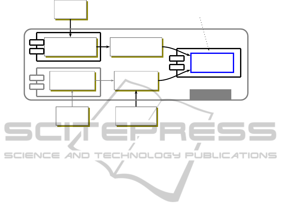
The proposed system of inference, and its architec-
ture, using the semantic tableaux method for BPMN
models is presented in Fig. 1. The system works auto-
matically and consists of some software components.
The first component (the “TL Formulas Generator”
module) provides the functionality to produce a log-
ical specification. Logical specification is a set of
many temporal logic formulas. Formula generation
is performed by extracting directly from the design
patterns in the BPMN model. The extraction is fo-
cused on BPMN patterns and is shown later in this
work. Formulas are collected in a module (data ware-
house, i.e. file or database) that stores the specification
of the system (the “System’s Specification” module).
Properties of the system are treated as a conjunction
of formulas p
1
∧ . . . ∧ p
n
= P. The third component
(the second one is discussed later) provides the de-
sired properties of the system expressed in temporal
logic formulas (the “System’s Properties” module).
The easiest way to obtain such a formula is (manual)
ICAART 2012 - International Conference on Agents and Artificial Intelligence
326
BPMN
MODEL
TL FORMULAS
GENERATOR
TL QUERY
GENERATOR
BPQL
MODEL
SYSTEM’S
SPECIFICATION
SYSTEM’S
PROPERTIES
TL QUERY
EDITOR
TEMPORAL
PROVER
p
1
∧ .. . ∧ p
n
⇒ Q
SYSTEM
Figure 1: The architecture of an automatic and deduction-based business process verification system.
identification of the desired property Q using any for-
mula editor for temporal logic (the “TL Query Edi-
tor” module). Formulas are stored in a separate mod-
ule (data warehouse, e.g. file). Another way to ob-
tain a property is by using BPQL (Business Process
Query Language). This way of obtaining the formulas
will not be examined in this paper since it seems to be
the next step in research and has been mentioned here
in order to obtain a more broader perspective. Both
the specification of a system and the examined prop-
erties are input to a module (the “Temporal Prover”
module), which is the second component mentioned
above, for automated reasoning in temporal logic us-
ing the semantic tableaux method, i.e. the Semantic
Tableaux Temporal Prover. The input for this module
is the formula P ⇒ Q, or, more precisely:
p
1
∧ .. . ∧ p
n
⇒ Q (1)
After the negation of a formula 1, it is placed at the
root of the inference tree. Then, the formula is decom-
posed using well-defined rules of the method. Finding
a contradiction in all branches of the tree means no
valuation satisfies a formula placed in the root. When
all branches of the tree have contradictions, it means
that the inference tree is closed. This consequently
leads to the statement that the initial formula 1 is true.
Recently, two deduction engines were designed
and implemented for the smallest linear and future
temporal logic of class K. They work and inference
using the semantic tableaux method, which means
that the first prototype versions of the “Temporal
Prover” module in Fig. 1 is ready. The generation
component of the system specification (the “TL For-
mulas Generator” module) is currently in preparation
and its theoretical aspects are discussed below.
4 EXTRACTION AND
GENERATION OF FORMULAS
Acquisition of formulas, i.e. linear time tempo-
ral logic formulas, is essential for construction of
any logical specification of a system, can be called
the bottleneck of the specification creation process.
Therefore, all efforts towards automation of this phase
are very desirable, since manual creation of such
a specification, usually consisting of a large number
of logical formulas can be monotonous and error-
prone, not to mention the fact that the creation of
such a specification can be difficult for inexperienced
users.
The proposed method for automatic extraction of
a logical specification is based on the assumption that
the whole business model is built using only well-
known design patterns of BPMN. This assumption
cannot be regarded as a restriction and it enables
generation of good business models. Therefore, the
whole process of building a logical specification in-
volves the following steps:
1. analysis of a business model aimed to extract all
business patterns,
2. translation the business model with extracted pat-
terns to a logical expression (similar to a well-
known regular expression),
3. generation a logical specification from the logical
expression, i.e. a set of formulas of linear time and
TOWARDS FORMAL AND DEDUCTION-BASED ANALYSIS OF BUSINESS MODELS FOR SOA PROCESSES
327

minimal temporal logic.
Let us introduce formal definitions necessary for the
presented steps. This will enable illustration of the
entire procedure in a formal way.
The temporal logic alphabet consists of a count-
able set of atomic formulas, classical logic connec-
tives, parentheses and two linear temporal logic op-
erators 2 and 3. Definition of a well-formed for-
mula of linear time temporal logic LTL is based on
the BNF notation and it can be found in many works,
e.f. (Emerson, 1990). Further definitions refer to de-
sign patterns of BPMN. An elementary set of for-
mulas over atomic formulas a
i
, where i = 1, . . . , n,
which is denoted pat(a
i
), is a set of temporal logic
formulas f
1
, ..., f
m
such that all formulas are well-
formed. For example, an elementary set pat(a, b, c) =
{2¬(a∨b), a ⇒ 3c} is a two-element set of LTL for-
mulas, created over three atomic formulas.
Business models can be quite complex and may
contain nesting patterns. Logical expression W
L
al-
lows for description of complex models is a structure
created using the following rules:
• every elementary set pat(a
i
), where i > 0 and a
i
is an atomic formula, is a logical expression,
• every pat(A
i
), where i > 0 and A
i
is either
– a sequence of atomic formulas, or
– a set pat(a
j
), where j > 0 and a
j
is an atomic
formula, or
– a logical expression pat(A
j
), where j > 0
and also is a logical expression,
• if pat
1
() and pat
2
() are logical expressions, where
empty parentheses mean any arguments, then
their concatenation pat
1
() · pat
2
(), also noted
pat
1
()pat
2
(), is a logical expression as well.
The last rule is a special case and is redundant since
every sequence of actions can always be described as
a sequence of sequences.
A logical expression enables representation of ar-
bitrary combination of temporal logic formulasets de-
scribing a business model and enables generation of a
logical specification. Logical specification L consists
of all formulas derived from a logical expression, i.e.
L(W
L
) = { f
i
: i > 0}, where f
i
is any temporal logic
formula. Generation is not a simple summation of for-
mula collections resulting from a logical expression
and its components and it has two inputs. The first
one is a logical expression W
L
and the second one is
a predefined set of temporal formulas for every de-
sign pattern. Below is shown a first section of such
a file which contains formulas for the Basic Control
Patterns.
/* version 23.07.2011
/* Basic Control Patterns
Sequence(f1,f2):
f1 => <>f2
Parallel-Split(f1,f2,f3):
f1 => <>f2 & <>f3
[]˜(f1&(f2|f3))
Synchronization(f1,f2,f3):
f1 & f2 => <>f3
[]˜(f3&(f1|f2))
Exclusive-Choice(f1,f2,f3):
f1 => (<>f2 & ˜<>f3)|(˜<>f2 & <>f3)
[]˜(f2 & f3)
Simple-Merge(f1,f2,f3):
f1|f2 => <>f3
[]˜(f3&(f1|f2))
/* ..... [other] Patterns
Formulas describe both safety and liveliness proper-
ties of each pattern if necessary. f
1
, f
2
etc. are atomic
formulas for a pattern.
The sketch of the generation algorithm is as fol-
lows:
• at the beginning, the logical specification is
empty, i.e. L =
/
0;
• the most nested pattern or patterns are processed
first, and next, less nested patterns are processed
one by one, i.e. patterns that are located more to-
wards the outside;
• if the currently analyzed pattern consists only
of elementary arguments, i.e. atomic formulas,
the logical specification is extended by formulas
linked to the type of the currently pattern pat(),
i.e. L = L ∪ pat(), for example, SeqSeq(p, q, r),
gives L = {p ⇒ 3q, q ⇒ 3r}, and ParSp(a, b, c)
gives L = {a ⇒ 3b∧ 3c, 2¬(a ∧ (b∨ c))};
• if any argument is a pattern itself, then the logical
disjunction of all its arguments, including nested
arguments, is substituted in place such a pattern,
for example, ParSp(Seq(a, b), c, d) leads to L =
{a ⇒ 3b} ∪ {(a ∨ b) ⇒ 3c ∧ 3d, 2¬((a ∨ b) ∧
(c∨d))}.
Let us consider a simple example to illustrate the
approach. The example is a combination of three pat-
terns: Sequence, Parallel-Split and Synchronization.
Suppose that after analysis of documents (Analys-
Docum or shortly a) an offer is prepared (PrepOffer
or b) and sent using both fax (SendFax or c) and mail
(SendMail or d). After receiving the fax (ReceivFax
or e) and the mail (ReceivMail or f), an offer is regis-
ICAART 2012 - International Conference on Agents and Artificial Intelligence
328

tered (RegistOffer or g). The logical expression is
SeqSeq(AnalysDocum,
ParSp(PrepOf f er, SendFax, SendMail),
Synch(ReceivFax, ReceivMail, RegistOf fer))
or after the substitution:
SeqSeq(a, ParSp(b, c, d), Synch(e, f, g))
At the beginning, the logical specification is L =
/
0
and next it is built in the following steps. The most
nested specification is Parallel-Split, which gives L =
L ∪ {b ⇒ 3c ∧ 3d, 2¬(b ∧ (c ∨ d))}, and then Syn-
chronization L = L∪ {e∧ f ⇒ 3g, 2¬(g∧ (e∨ f))}.
The assembly of patterns requires consideration of ar-
guments’ conjunction L = L∪{a ⇒ 3(b∨ c∨d), (b∨
c∨ d) ⇒ 3(e∨ f ∨g)}. Thus, the resulting specifica-
tion contains formulas
L = {b ⇒ 3c∧ 3d, 2¬(b∧ (c∨ d)),
e∧ f ⇒ 3g, 2¬(g∧ (e∨ f )),
a ⇒ 3(b ∨ c∨ d), (b∨ c∨ d) ⇒ 3(e∨ f ∨ g)} (2)
The examined property can be a ⇒ 3g and the whole
formula to be analyzed using the semantic tableaux
method is
(b ⇒ 3c ∧ 3d) ∧ 2¬(b∧ (c∨ d)) ∧
(e∧ f ⇒ 3g) ∧ 2¬(g∧ (e∨ f)) ∧
(a ⇒ 3(b ∨ c∨ d)) ∧
((b∨ c∨ d) ⇒ 3(e∨ f ∨ g)) ⇒ (a ⇒ 3g) (3)
Formula 2 represents the output of the “TL Formu-
las Generator” module in Fig. 1. Formula 3 provides
a combined input for the “Temporal Prover” mod-
ule in Fig. 1, and of course also for the implemented
prototype engines. Presentation of a full reasoning
tree for formula 3 exceeds the size of the work. The
tree contains nearly four hundred nodes, and all of its
branches are closed.
5 RELATED WORKS AND
CONCLUSIONS
Let us discuss some related works. Work (Eshuis
and Wieringa, 2004) uses UML activity diagrams for
specification, and the goal is to translate diagrams into
a format that allows model checking. Another im-
portant research direction is verification of business
processes using Petri nets (der Aalst, 2002). A differ-
ent direction for verification is π-calculus (Ma et al.,
2008). All of the research themes mentioned above
are different from the approach presented in this work
and work (Klimek et al., 2010) represents a very pre-
liminary version of ideas developed here.
The work presents a new approach to business
model verification which is based on temporal logic
and a semantic tableaux prover. The paper presents
an algorithm for transformation of design patterns in a
BPMN diagram to the logical expressions which rep-
resent the BPMN model. This allows for construction
of logical specifications in an automated way. The ad-
vantage of the methodology is providing innovative
concept for process verification which might be done
for any given business model created using the BPMN
notation. Future research should extend the results to
all patterns of BPMN model.
ACKNOWLEDGEMENTS
This work was supported by the AGH UST internal
grant no. 11.11.120.859.
REFERENCES
Benthem, J. V. (1993–95). Handbook of Logic in Artificial
Intelligence and Logic Programming, chapter Tempo-
ral Logic, pages 241–350. 4. Clarendon Press.
Clarke, E., Wing, J., and et al. (1996). Formal methods:
State of the art and future directions. ACM Computing
Surveys, 28 (4):626–643.
D’Agostino, M., Gabbay, D., H¨ahnle, R., and Posegga, J.
(1999). Handbook of Tableau Methods. Kluwer Aca-
demic Publishers.
der Aalst, W. M. P. V. (2002). Making work flow: On the
application of petri nets to business process manage-
ment. In ICATPN, volume 2360 of LNCS, pages 1–12.
Springer–Verlag.
der Aalst, W. M. V., ter Hofstede, A., Kiepusewski, B., and
Barros, A. (2003). Workflow patterns. Distributed and
Parallel Databases, 4(1):5–51.
Emerson, E. (1990). Handbook of Theoretical Computer
Science, volume B, chapter Temporal and Modal
Logic, pages 995–1072. Elsevier, MIT Press.
Eshuis, R. and Wieringa, R. (2004). Tool support for ver-
ifying uml activity diagrams. IEEE Transactions on
Software Engineering, 30 (7):437–447.
Klimek, R., Skrzy´nski, P., and Turek, M. (2010). Deduc-
tion based verification of business models. In Kor-
czak, J., Dudycz, H., and Dyczkowski, M., editors,
Advanced Information Technologies for Management,
volume 147 of Research Papers of Wroclaw Univer-
sity of Economics, pages 173–188. Publishing House
of Wrocaw University of Economics.
Ma, S., Zhang, L., and He, J. (2008). Towards formaliza-
tion and verification of unified business process model
TOWARDS FORMAL AND DEDUCTION-BASED ANALYSIS OF BUSINESS MODELS FOR SOA PROCESSES
329

based on pi calculus. In Proc. ACIS International Con-
ference on Software Engineering Research, Manage-
ment and Applications, pages 93–101.
OMG (2009). Business process modeling notation specifi-
cation, version 1.2,. Technical report, January 2009,
OMG Document dtc/2009-01-03.
Ouyang, C., Dumas, M., ter Hofstede, A., and van der Aalst,
W. M. P. (2006). From bpmn process models to bpel
web services. In IEEE International Conference on
Web Services (ICWS’06), pages 285–292.
Riehle D., Z. H. (1996). Understanding and using patterns
in software development. Theory and Practice of Ob-
ject Systems, 2(1):3–13.
ICAART 2012 - International Conference on Agents and Artificial Intelligence
330
