VERTICAL MOVEMENT CONTROL OF QUAD-THRUST
AERIAL ROBOT
Design, Analysis and Experimental Validation
Roman Czyba and Grzegorz Szafranski
Department of Automatic Control and Robotics, Silesian University of Technology, Akademicka 16, Gliwice, Poland
Keywords: Attitude Control, Altitude Control, Infrared Rangefinder, Unmanned Aerial Vehicle, Quad-Thrust Aerial
Robot.
Abstract: In this paper we focus on the problem of the vertical movement control and approach to control algorithm
implementation for unmanned aerial vehicle (UAV), known as a quadrotor. The most important control
subsystems for the VTOL (Vertical Take-Off and Landing) are the attitude stabilization and the altitude
regulation. Both systems are presented in this paper. However, the vertical movement of the platform has
been confined to precise operations such as taking-off and landing. These actions demand high reliability
and they are very crucial for autonomous flights. The design, analysis and the validation tests have been
undertaken on the experimental aerial platform.
1 INTRODUCTION
In recent years, there has been rapid development of
unmanned aerial vehicles (UAVs) and micro aerial
vehicles (MAVs). These have become known as
”robotic aircraft”, and their use has become very
wide. They can be classified according to their
application for military or civil use (Nonami, 2010).
The attitude controller is an important feature
since it allows the vehicle to maintain a desired
orientation and, hence, prevents the quadrotor from
crashing when the pilot performs the desired
manoeuvre. On the other hand altitude of flight
depends directly on the general thrust of all four
motors. Therefore, to relieve the operator from the
throttle continuous operation, the altitude control
system was applied to adjust the height of the flight.
The attitude and altitude control problem of a
VTOL-UAVs has been investigated by several
researchers and a wide class of controllers has been
proposed (Castillo, 2005), (Tayebi, 2006),
(Valavanis, 2007), (Bouabdallah, 2007), (Nonami,
2010).
The main aim of this research effort is to
examine the effectiveness of a designed attitude
stabilization and altitude regulation control system
for quadrotor. The paper is organized as follows.
First, an experimental platform with an indication of
technical solutions is introduced. The second part
includes a mathematical description of the nonlinear
quadrotor model. The next section presents a general
scheme of control system which consists of two
subsystems: MIMO attitude stabilization and altitude
regulation. Finally, the results of experiments in the
HiL structure (Hardware in the Loop) are shown.
The conclusions are briefly discussed in the last
section.
2 THE QUADROTOR SYSTEM
DESCRIPTION
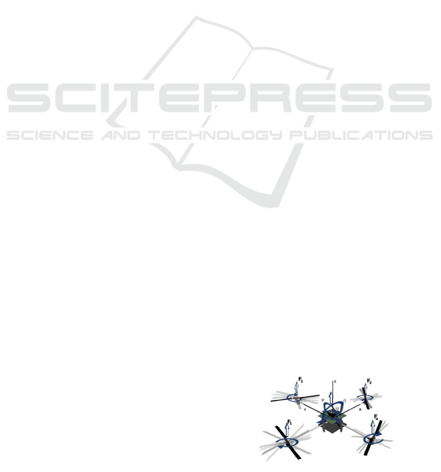
The aerial vehicle consists of a rigid cross frame
equipped with four rotors as shown in Figure 1.
Figure 1: Quadrotor concept motion description.
287
Czyba R. and Szafranski G..
VERTICAL MOVEMENT CONTROL OF QUAD-THRUST AERIAL ROBOT - Design, Analysis and Experimental Validation.
DOI: 10.5220/0003460602870290
In Proceedings of the 8th International Conference on Informatics in Control, Automation and Robotics (ICINCO-2011), pages 287-290
ISBN: 978-989-8425-75-1
Copyright
c
2011 SCITEPRESS (Science and Technology Publications, Lda.)
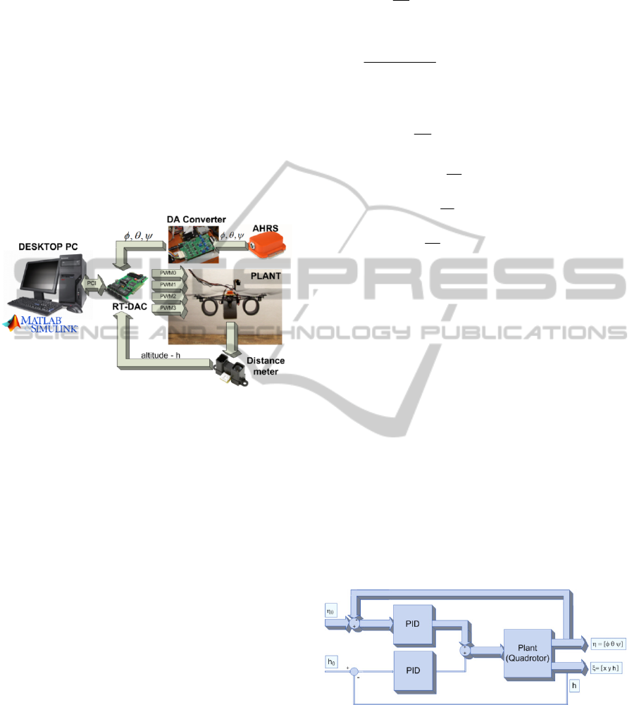
During experiments we use the setup which
consists of: quadrotor airframe with propulsion
system, AHRS, PC with I/O card and RC
transmitter. The frame composed of carbon tubes
attached to a plastic hub, and at the other ends with
propulsion systems. Four propulsion systems, each
one is composed of a brushed DC-motor driven by
PWM signal. The miniature MTi Xsens AHRS
estimates with a Kalman filter the 3D orientation
data and gives the calibrated data of acceleration and
angular velocity. The Matlab and Simulink software
in combination with Real-Time Workshop and RT-
CON allows an easy implementation of the control
system in block diagram format via Simulink.
Figure 2: Quadrotor test bench.
This structure of experimental setup was used for
a fast prototyping of designed control system, as
well as the attitude and altitude control system
concept, in the hardware in the loop system
(Figure 2).
3 MATHEMATICAL MODEL
OF THE QUADROTOR
The quadrotor is a six degrees of freedom system
defined with twelve states. The following state and
control vectors are adopted:
,,,, , ,,,,,,
⎡⎤
⎣⎦
T
X
xxyyzz
(1)
1234
,,,
⎡⎤
⎣⎦
T
Uuuuu
(2)
where:
i
u – control input of motor,
,,
T
x
yz
–
position coordinates,
,,
T
– Euler angles,
The dynamic model is derived using Euler-
Lagrange formalism (Bouabdallah, 2007), (Castillo,
2005), (Goel, 2009).
Finally the quadrotor dynamic model with x,y,z,
motions as a consequence of a pitch, roll and yaw
rotations is as follows:
2
1
xx zz
xx
zz
IIsc
I
Ic T
(3)
2
1
1
2 2
zz
yy
zz yy zz
Is c s
Is
I
IIcT
(4)
1
zz
zz
Is T
I
(5)
g
f
xs
m
(6)
g
f
ycs
m
(7)
g
f
zccg
m
(8)
where: s,c abbreviations of ’sin’ and ’cos’,
,,
x
xyyzz
I
II
– inertia moments, f
g
– total thrust,
T
T
T
torques.
4 SCHEME OF CONTROL
SYSTEM
A general scheme of control system (Figure 3)
consists of two subsystems: attitude stabilization
around hovering conditions and altitude regulation.
Both of control systems were designed based on
the PID algorithm, but between them exists
sufficient time-scale separation. It is achieved
through proper selection of controller parameters.
Applied fast prototyping methodology allows to tune
the controller parameters through HiL (Hardware in
the Loop) experiments.
Figure 3: Block diagram of control system.
4.1 Attitude Stabilization
The quadrotor model described by equations (3)(8),
will be used to design the attitude control system that
achieves the angular stabilization and regulation.
The control task is stated as a tracking problem for
the following variables:
ICINCO 2011 - 8th International Conference on Informatics in Control, Automation and Robotics
288
0
lim 0
t
tt
⎡⎤
⎣⎦
(9)
0
lim 0
t
tt
⎡⎤
⎣⎦
0
lim 0
t
tt
⎡⎤
⎣⎦
where
00 0
,,tt t
are the desired values of
the considered variables (roll angle, pitch angle, yaw
angle respectively).
4.2 Low Level Altitude Control
The main task of the altitude control system is to
achieve and remain in a desired position calculated
along the z-axis direction. The reference value can
be either the constant level above the ground or a
trajectory defined for take-off and landing
manoeuvres. The height measurement is
accomplished using an infrared rangefinder.
4.2.1 Distance Measurement
To provide altitude data for the unmanned aerial
robots some different approaches are possible. One
of the sensors that gives straight information about
the distance or altitude are infrared rangefinders.
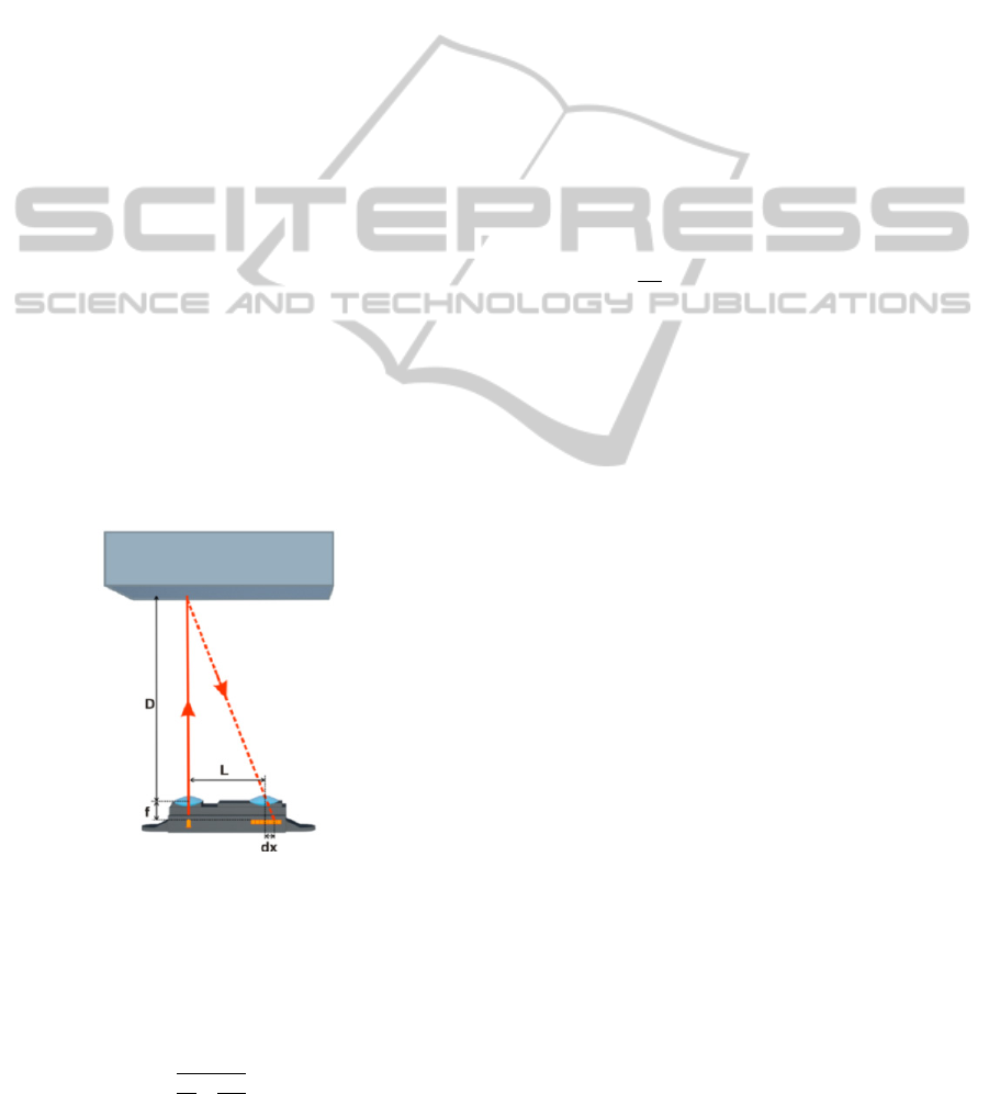
An infrared sensor is a distance measuring unit
which consist of an integrated combination of PSD
(position sensitive detector), IRED (infrared emitting
diode) and signal processing circuit.
Figure 4: IR sensor theory of operation.
The principle of operation is based on the
triangulation method, so sensor cannot be easily
affected by the perturbations.
In theory the distance between object and sensor
is calculated from the following formula:
=
+
1
(10)
where: D - measured distance, L - distance
between transmitter and receiver, f - focal length, α –
angle of transmitter, dx – position on PSD.
The main disadvantage is that the relationship
between the measured distance and voltage is
nonlinear.
4.2.2 Controller Design
The differential equation for z-axis movement (in the
chapter 3) gives the basic information about the
quadrotor dynamics. This equation (11) has been
combined with the model of the propulsion system.
On the basis of the dynamics comparison between
the rigid body and motors, in our case the motor
dynamics has been neglected. Only static
relationship between generated thrust force and
applied voltage to the motors is introduced (12).
Such simplified model has been tested in
Matlab/Simulink environment.
g
m
f
h
g
)cos()cos(
(11)
2
4
ukDCF
nTTi
(12)
∑
4
1i
Tig
Ff
(13)
The PID parameters have been obtained during
the simulation experiments. The results are presented
in the next chapter.
5 TESTS AND RESULTS
In this section, we present the results of experiments
which were conducted on the quad-thrust aerial
robot, to evaluate the performance of a designed
attitude and altitude control system. At first, in order
to obtain some basic knowledge about the dynamics
of quadrotor, a simulation system was developed
under Matlab/Simulink platform. The impact of the
angular stabilization to the altitude control has been
tested and verified during the simulation and
experiments (Figure 5).
An autonomous start and landing of the quad-
thrust aerial robot are presented in Figure 6.
The platform descends according to the ramp
signal which ensures smooth landing and touching
the ground. Results of attitude stabilization during
the altitude control are presented in Figure 7.
VERTICAL MOVEMENT CONTROL OF QUAD-THRUST AERIAL ROBOT - Design, Analysis and Experimental
Validation
289
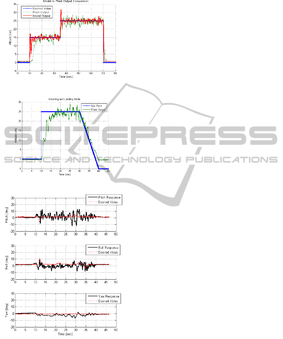
Figure 5: Altitude control. Model and plant comparison.
Figure 6: Autonomous take-off and landing.
Figure 7: Angular stabilization during the altitude control.
6 CONCLUSIONS
The quad-thrust aerial robot can make possible
plenty of potential applications for unmanned aerial
vehicles. In this paper we have presented the
quadrotor dynamics. Designed control system
consists of the angular stabilization and altitude
regulation of the platform. In case of attitude
stabilization the problem of different dimensions
between inputs and outputs was solved by the
MIMO PID controller and output block which
allows the control algorithm to be accomplished. In
case of altitude control some model simplification
has been made in order to achieve the controller
parameters. Taking into consideration the limitations
of the IR sensor, the altitude control works
surprisingly well. Presented solution can be applied
in both the indoor and outdoor environment as well.
The achieved results are satisfactory. The main
disadvantage is the limitation in the height
measurement but it is allowed to perform precise
manoeuvres, such as taking-off and landing.
ACKNOWLEDGEMENTS
This work has been granted from funds for science
in 2010-2012 as a development project No.
OR00011811.
REFERENCES
S. Bouabdallah, 2007. Design and Control of Quadrotors
with Application to Autonomous Flying. Ph.D.
dissertation, School of Computer and Communication
Sciences, Lausanne.
P. Castillo, R. Lozano, and A. E. Dzul, 2005. Modelling
and Control of Mini-flying Machines. Springer-Verlag,
2005, ch. 3.
R. Czyba, 2010. Attitude Stabilization of an Indoor
Quadrotor. Proc. Of European Micro Aerial Vehicle
Conference and Competition, EMAV.
A. Tayebi and S. McGilvray, 2006. Attitude stabilization
of a VTOL quadrotor aircraft. IEEE Trans. on Control
Systems Technology, vol. 14, no. 3, 2006, pp. 562-
571.
K. P. Valavanis, 2007. Advances in Unmanned Aerial
Vehicles. Springer-Verlag, 2007.
K. Nonami, F. Kendoul, S. Suzuki, W. Wang, D.
Nakzawa, 2010. Autonomous Flying Robots. Spirnger,
1
st
edition.
R. Goel, S. M. Shah, N. K. Gupta, N. Ananthkrishnan,
2009. Modeling, Simulation and Flight of an
Autonomous Quadrotor. Proceedings of ICEAE.
ICINCO 2011 - 8th International Conference on Informatics in Control, Automation and Robotics
290
