
SKETCH-BASED BUILDING MODELLING
David J. Olsen, Nathan D. Pitman, Sutirtha Basak and Burkhard C. W
¨
unsche
Department of Computer Science, University of Auckland, Private Bag 92019, Auckland, New Zealand
Keywords:
Sketch-based modelling, Sketch-based interfaces, Virtual environments, Displacement mapping.
Abstract:
Computer generated 3D models of buildings are an important component of many computer graphics applica-
tions. Rapid and easy-to-use modelling techniques are often more important than the ability to create precise
and detailed geometry. We present a sketch-based modelling tool for the rapid creation of rough 3D building
models. The algorithm analyses the sketch input, extracts shape and detail information, predicts the build-
ing type, creates 3D models using three different reconstruction techniques, and adds building details using a
displacement texture. A user study confirms that the algorithm is easy to use, intuitive, efficient and fun.
1 INTRODUCTION
Computer generated 3D models of buildings are an
important component of many virtual environments
including urban design, video games, virtual worlds,
visual impact studies, architecture and archaeology.
In many applications rapid modelling (prototyping) is
more important than precision and meticulous details.
In game development in particular, there has been
a trend toward roughing out designs to evaluate the
overall concept before investing the effort involved in
detailed design. This stage of development is often
referred to as white-boxing (Byrne, 2005). Sketch-
based interfaces are an attractive solution for this type
of application since they are intuitive (pen-and-paper
metaphor), encourage creativity, and enable users to
concentrate on the overall problems rather than de-
tails. This trend is likely to strengthen further with
the advent of cheap and reliable touchscreen technol-
ogy (Windows 7, iPhone, iPad) and haptic interfaces.
In this paper we present a novel algorithm for the
rapid design of 3D buildings from basic 2D sketch
input. We motivate the design of our algorithm by
evaluating users’ drawings and mental models of 3D
buildings. We develop algorithms for sketch classifi-
cation and mapping the 2D sketch input to 3D geom-
etry representing the building shape and displacement
textures containing geometric details.
Section 2 reviews relevant previous work in
sketch-based modelling and building modelling. Sec-
tion 3 presents a user study investigating how inexpe-
rienced users sketch buildings. From this we derive
the design requirements for our application. Section 4
presents the design of the system. We evaluate our
application in section 5 and conclude the paper and
offer suggestions for future work in section 6.
2 LITERATURE REVIEW
Existing tools for building creation can be differenti-
ated into two types: libraries of building models and
components allow users to assemble them into new
buildings (Artifice Inc., 2010). These tools are easy to
use, but restrict the user’s creativity and limit the style
and shape of buildings. On the other extreme there
are fully-featured and extensible modelling tools such
as AutoCAD and Maya, which enable the construc-
tion of detailed 3D models with a precision and level-
of-detail required by architects and engineers. These
tools suffer from complex interfaces and a steep learn-
ing curve, and require creativity and the ability to con-
struct 3D mental models, hence making them unsuit-
able for inexperienced users. Specialised software for
building modelling has also been produced, e.g., (Iron
Perth, 2010), but still suffers from a complex interface
and a steep learning curve.
The work closest to our research is the “sketch-
ing reality” technique, which is capable of generating
detailed and textured models of buildings from a per-
spective drawing of a single view (Chen et al., 2008).
This is achieved by analysing the sketch for junctions,
edges and faces, and using probabilistic techniques to
map it to a model which satisfies any specified archi-
119
J. Olsen D., D. Pitman N., Basak S. and C. Wünsche B..
SKETCH-BASED BUILDING MODELLING.
DOI: 10.5220/0003377501190124
In Proceedings of the International Conference on Computer Graphics Theory and Applications (GRAPP-2011), pages 119-124
ISBN: 978-989-8425-45-4
Copyright
c
2011 SCITEPRESS (Science and Technology Publications, Lda.)
tectural constraints and resembles known topologies.
The resulting models not only capture large scale
shape, structure and topology, but also smaller details
and features such as windows, doors and pillars. Nev-
ertheless, the method requires detailed and accurate
perspective drawings, and is hence only suitable for
experienced users such as architects, artists and de-
signers.
Cherlin et al. present a comparatively lightweight
and much more minimal and accessible system for
sketch-based modelling of general objects (Cherlin
et al., 2005). While the authors did not apply their
technique to the modelling of highly structured ob-
jects such as buildings, their goals are somewhat sim-
ilar to our research. Their focus lies in minimising
the number of strokes required in a sketch, and de-
veloping methods which draw parallels to the natural
sketching tendencies of users. Rivers et al. model a
shape from a set of orthographic projections of the
object, which is a popular representation in architec-
tural design (Rivers et al., 2010). The authors use
computer generated projections and not sketch input,
which would be unlikely to result in matching per-
spective projections.
3 REQUIREMENT ANALYSIS
A user study was employed to establish the scope
and requirements of our research, to gauge poten-
tial challenges, and to get indications for the design
of our sketch-based modelling tool. Details are de-
scribed in (Olsen et al., 2011). We concluded that
our sketch-based modelling tool should accept sketch
input of a 2D nature as sketching in 2.5D is fraught
with difficulty. Since most users drew the front face
of buildings, it was concluded that it would be suffi-
cient to work with one face and extrapolate the rest if
possible, rather than asking users to sketch multiple
faces. It was noted that skyscrapers tend to look sim-
ilar from all sides, whereas the same assumption can-
not be made for houses and other general buildings.
Rounded features present much difficulty as they in-
troduce ambiguity because it is not always clear ex-
actly which segments are rounded, e.g., a rounded
contour at the base could indicate a cone, cylinder or
an extruded conical cross section.
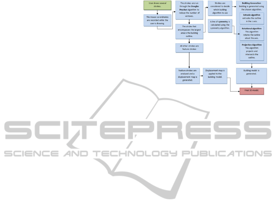
Figure 1: Overview of our algorithm for the sketch-based
modelling of buildings.
4 DESIGN
4.1 Design Overview
We have evaluated a large number photos of various
buildings from Google and found that many can be
characterised as follows: (1) Being roughly rotational
symmetric (e.g., towers); or (2) having an extruded
shape, e.g., warehouses; or (3) having a complex sil-
houette, which however looks similar from all sides,
e.g., many skyscrapers and castles. Most buildings
which do not fit these descriptions can be divided into
components belonging to the above three types, e.g.,
churches have usually an extruded shape for the nave
and a spire which looks similar from all sides. In or-
der to make the resulting models look interesting we
allow users to add detailed features to the sketches,
e.g., windows and doors.
We do not want to add complexity in the form
of annotations describing the type of building or fea-
ture. Our algorithm has therefore been designed in a
way that such classifications are made automatically
where required and otherwise that it gives a plausi-
ble result regardless of the semantic of a particular
sketch. We achieve this by classifying the building
type according to its contour and pattern of detailed
features. The features themselves are represented by
a displacement map which generates the illusion of
a complex geometry, without requiring information
about the type of represented shape. We found that
this works well for windows, doors, and other build-
ing features such as decorations in the facade.
Figure 1 gives a summary of our algorithm for
the sketch-based modelling of buildings. The follow-
ing subsections explain the various algorithm steps in
more detail.
GRAPP 2011 - International Conference on Computer Graphics Theory and Applications
120

4.2 Sketch Recognition
The user input sketches must be smoothed and ap-
proximated by polylines in order use them for the sub-
sequent polygonal modelling algorithms. We use the
Douglas-Peucker algorithm (Douglas and Peucker,
1973) to approximate user-input, eliminate minor
noise and generate a set of straight lines which closely
matches the original input sketch.
We then separate the building outline from detail
features (windows, doors, reliefs) and extraneous fea-
tures (trees, smoke, clouds, ground plane). We first
identify the building silhouette, i.e., we search for the
largest approximately closed shape in the sketch. Our
current prototype requires outlines to be sketched as
one single stroke. This is inconvenient, but hasn’t
proved a major problem in practice. Solutions com-
bining disjoint sketches have been proposed in the lit-
erature (Sun et al., 2006) and will be implemented
in the future. Sketches inside the building silhou-
ette form “detail features” (we require again closed
shapes) and sketches outside of it are classified as ex-
traneous features and are discarded. In many cases
users want to achieve symmetric building contours,
but produce skewed results. We have incorporated an
algorithm for symmetry detection (axis of symmetry)
and adjustment (Olsen et al., 2011).
4.3 Projection Algorithm
Many buildings do have a square footprint and look
similar from all sides, e.g., skyscrapers and castles.
For this type of buildings a realistic 3D model can be
generated by taking the user’s 2D sketch of the front
face, extruding it in z-direction, and projecting the
front face onto the other faces of the extruded model,
so that the resulting 3D model has the same projection
in x- and z-direction. There are infinitely many 3D ob-
jects corresponding to a 2D projection - the described
idea results in the largest such object. Note that the
outline of a sketch is a potentially concave polygon
which contains all strokes of a sketch.
The algorithmic realisation is surprisingly simple.
By extruding an outline polygon to infinity, we cre-
ate the largest possible object with the given outline.
By clipping each polygon of this object against the
outline on the other axis, we ensure that the object
is constrained to fit the outline on the other axis as
well. In practice we use an extrusion length slightly
larger than the bounding box of the input sketch. We
then project the outline polygon in z-direction and clip
all faces against it. The resulting polygons are then
again clipped against the outline polygon oriented in
x-direction using an algorithm described in (Glassner,
1995).
4.4 Extrusion Algorithm
Unlike skyscrapers, residential houses do not tend
to have similar silhouettes from the front and side.
Given a user’s 2D sketch of the front face of a house,
the back and side faces can be obtained by extrud-
ing the front face by a given depth d in z-direction.
We currently use a depth of 0.65 times the building
width. This has been motivated by analysing pic-
tures of warehouses and residential houses and by the
fact that the value
width
depth
=
1
0.65
≈ 1.54 is close to the
golden ratio
1=
√
5
2
≈ 1.62 which has been shown to
be aesthetically pleasing. In reality this ratio varies
widely and we are considering giving the user some
control over the extrusion depth using sketch input.
4.5 Rotation Algorithm
Many building structures, such as towers, are rotation
symmetric. The identification of rotation symmetric
shapes is explained in the next section. We generate
the 3D geometry by determining an axis of rotation
and generating a surface-of-revolution by rotating the
sketched cross section around the axis. A common
problem is that the user sketch is not exactly symmet-
ric. We have incorporated an algorithm for symme-
try detection and correction (Olsen et al., 2011). The
number of segments of the rotated shape is by default
set high enough to generate a visually smooth curved
surface, but the user can change this parameter in a
menu. The higher the segment number, the rounder
the base - a segment number of 4 yields a square base
building. In future versions of this algorithm we want
to estimate the number of sections of the surface-of-
revolution from the users sketch input.
4.6 Automatic Detection of Building
Types
Selection between the projection algorithm and the
extrusion algorithm is performed based on the dimen-
sion of the sketched building outline, the shape of the
outline, and the number of internal features. If the
building is more than 50% taller than it is wide, it is
assumed to be some kind of tower and the projection
algorithm is used. Similarly the projection algorithms
is used if the building has more than 6 internal fea-
tures or if the contour has more than 10 sample points.
The motivation for this is that many detailed features,
such as windows, indicate large buildings such as of-
fice buildings, which should look consistent from all
SKETCH-BASED BUILDING MODELLING
121

sides. A detailed silhouette would look unnatural if
extruded in one direction and having the same look
from the front and side usualy results in a visually
more pleasing shape for complex contours.
It was observed in the user study that rounded
structures are typically drawn with a curve at the base,
hence the rotation algorithm is selected if a curved
stroke is detected at the base of a building. A stroke
is determined to be curved if its Douglas Peucker re-
duction meets the following condition:
1. The angle between the first and last segment is
between 20
◦
and 180
◦
.
2. No difference in angle between consecutive seg-
ments is greater than 30
◦
.
3. The average curvature (angle/distance) is greater
than 1.3 times the standard deviation of the curva-
ture.
The final condition serves to reject curves that bend
both ways, or are not smooth enough. All of the val-
ues were selected empirically, with the first two con-
ditions set conservatively such that they simply reject
strokes that are clearly not curves. The final condition
required more careful adjustment. Ideally, different
parts of the building could be identified as rounded
separately. At this stage, however, if one or more
curved strokes are found, the entire building is as-
sumed to be rotationally symmetric.
If none of the conditions for the projection and
rotation algorithm are fulfilled, then we choose the
extrusion algorithm.
4.7 Relief Mapping
The user study in section 3 demonstrated that most
users like to add features such as windows and doors
to a building sketch. Adding these features to the
resulting 3D model is desirable since it makes the
model look more natural, interesting, and distinguish-
able. Representing sketched building features with
texture maps results in a flat unnatural look, whereas
constructing 3D geometry could lead to very complex
shapes and is difficult to apply to rounded surfaces.
We therefore decided to represent sketched building
features with a relief map (displacement map).
The displacement maps need to be generated au-
tomatically from the user sketch input, ideally with
no extra user actions required. Since we do not want
to require annotations, and extracting semantic with-
out annotation is difficult we decided to represent all
closed features within the building outline with a dis-
placement map. If the user draws on top of an ex-
isting feature outline the new intersecting shape will
be reversed. The displacement map is represented by
a 2D gray scale image where 127 represents no dis-
placement. Values smaller or larger than this value
displace surface points inside or outside the wall, re-
spectively. As mentioned before detail features are
detected as strokes lying within the building outline.
The strokes are approximated with a polyline using
the Douglas-Peucker algorithm and then associated
with an appropriate position on the displacement map.
The displacement values within the feature sketch are
set by using a scan line conversion algorithm.
5 RESULTS
We evaluated our algorithm using a three-step ap-
proach: First we tested whether the pictures drawn
in the original user study would result in plausible 3D
building models. Secondly we searched for a variety
of real buildings on the Internet and tried to recre-
ate them using our tool. Thirdly we performed a user
study evaluating the effectiveness, intuitiveness and
ease-of-use of our application.
5.1 Creation of Building Models from
Paper Sketches
In order to test our program with the results from
the initial user study we replicated some of the paper
drawings in our sketch interface. Most results looked
visually pleasing and plausible as illustrated in fig-
ure 2. The top of the figure shows an industrial build-
ing drawn by one of the participants in our user study.
Our program has correctly detected that the extrusion
algorithm is most appropriate. Features, though a bit
uneven, appear as drawn, and extruding inwards is
shown to be a reasonable assumption. The bottom of
the figure shows an ambiguous sketch of a skyscraper.
It is unclear whether the building is round, square with
a dome on top, or simply extruded. Our application
selects the projection algorithm, which yields a natu-
ral and attractive looking result.
Buildings containing differently shaped compo-
nents, such as a house with a chimney or a church
with a wide nave and narrow spire can not be mod-
elled in one step as illustrated in figure 3.
5.2 Sketch-based Modelling of Real
Buildings
The second set of evaluations involved using pho-
tographs of real buildings and modelling them using
our application. Figure 4 shows that the resulting
models are visually attractive and represent a good
GRAPP 2011 - International Conference on Computer Graphics Theory and Applications
122
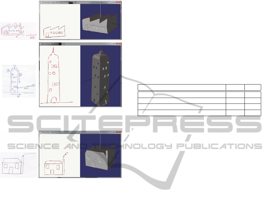
Figure 2: A sketch and resulting model of an industrial
building (top) and of a skyscraper (bottom).
Figure 3: A failure case: a house and chimney can not be
modelled in one step since the same extrusion depth will be
applied to both components resulting in an unnatural look.
approximation of the original buildings. All of the
building models were created in less than a minute.
Some problems can be observed: the roof of the
3D model of the warehouse has a bend due to a bend
in the input sketch, which was not eliminated by the
Douglas-Peucker algorithm. While straighter lines
could be obtained by increasing the epsilon-value of
the algorithm, this would also smooth out intended
features. For the castle the tower in the middle of the
silhouette is replicated not only along the outside of
the shape, but also in the middle of the model. In
general, if we have an outline with k bulges then the
resulting 3D model will have k ×k 3D bulges. Also
note that the towers have a square shape rather than
rounded as in the photo. Another problem which can
be observed is, that it is difficult to sketch all detail
features of a large building, e.g., all windows of a
skyscraper. This issue could be resolved by filling the
input sketch with detail features automatically based
on a user sketched example distribution (Guan and
W
¨
unsche, 2011).
5.3 User Study
In order to evaluate our application we asked nine
users to model the buidlings in 12 photos shown to
them (Olsen et al., 2011). The users were students
aged 21-23 with no or very limited modelling expe-
rience. The users were presented several statements
regarding modelling each building and they had to re-
spond by selecting an answer on a seven level Likert
scale ranging from “-3” (strong disagreement) to “3”
(strong agreement). The results of this evaluation (av-
erage of all buildings) are as follows:
Statement Mean σ
Easy to model (all images) 1.45 1.65
Model looked as expected (all images) 1.24 1.87
Tool is fun 2.16 1.19
Tool easier than other modelling tools 1.83 1.48
Several buildings could not be modelled with a
single object, resulting in lower scores. Some com-
plex objects such as a castle initially intimidated
users, which were subsequently pleasantly surprised
about how easy it was. Overall users were able to
quickly learn how to use our tool without additional
aid. They did not need to be told how the building
generation algorithms work as they were able to work
this out on their own. Users stated that it was easier
to use our tool than other 3D modelling tools they had
used or seen.
6 CONCLUSIONS AND FUTURE
WORK
We have a presented a novel algorithm for the sketch-
based modelling of buildings for use in rapid proto-
typing and applications where low detailed models
are sufficient. Our algorithm is based on a user study
observing how inexperienced users represent build-
ings, which suggests that 2D input without perspec-
tive information is the most intuitive representation.
In order to introduce a third dimension we have anal-
ysed existing buildings and then created three differ-
ent modelling algorithms based on extrusion, surfaces
of revolution, and an innovative projection-based al-
gorithm. The most suitable type of algorithm is auto-
matically determined by evaluating the input sketch.
For symmetric input sketches the axis of symmetry
is determined and the input sketch corrected to avoid
skewed results. Detailed features sketched within the
building are represented by a displacement map. Our
user evaluation suggests that the presented algorithm
is extremely intuitive (users were able to model build-
ings without any instructions) and fun to use. A wide
SKETCH-BASED BUILDING MODELLING
123
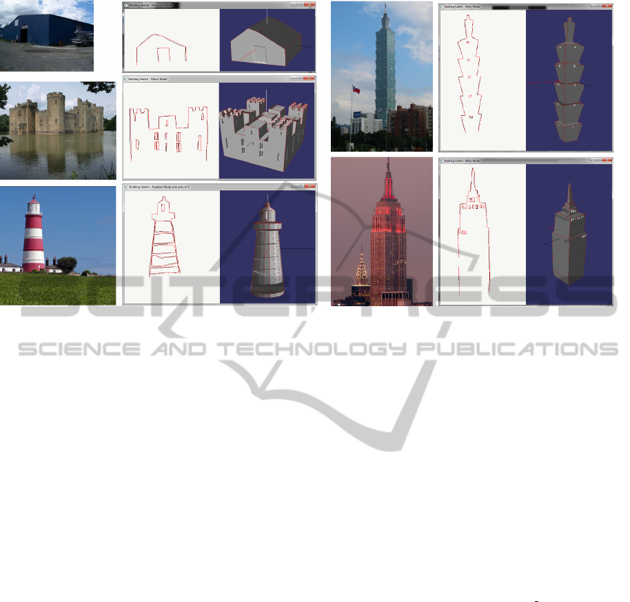
Figure 4: Sketch-based models of real buildings using photographs as basis for the input sketch. Starting from the top-left
corner moving in clockwise direction: a warehouse, Taipei 101, the Empire State building, a lighthouse and a castle.
variety of buildings can be successfully designed.
Current failure cases include complex rounded build-
ings, buildings with holes (e.g., the Eiffel tower), and
buildings containing components with different prop-
erties (e.g., a church with extruded nave and narrow
spire).
The presented work offers significant scope for fu-
ture research, in particular we require a component
wise construction of buildings. The selection of the
most appropriate modelling algorithm us still quite
simplistic. A more flexible method taking into ac-
count “sketched hints” might be more appropriate,
similar to curved strokes indicating round objects.
REFERENCES
Artifice Inc. (2010). Architecture Week - Great Buildings
Collection. http://www.greatbuildings.com.
Byrne, E. (2005). Game Level Design. Charles River Me-
dia.
Chen, X., Kang, S. B., Xu, Y.-Q., Dorsey, J., and Shum,
H.-Y. (2008). Sketching reality: Realistic interpreta-
tion of architectural designs. ACM Transactions on
Graphics, 27:11:1–11:15.
Cherlin, J. J., Samavati, F., Sousa, M. C., and Jorge, J. A.
(2005). Sketch-based modeling with few strokes. In
Proceedings of the 21st Spring Conference on Com-
puter Graphics, pages 137–145, New York, NY, USA.
ACM.
Douglas, D. and Peucker, T. (1973). Algorithms for the re-
duction of the number of points required to represent
a digitized line or its caricature. The Canadian Car-
tographer, 10(2):112–122.
Glassner, A. S. (1995). Clipping a concave polygon. In
Paeth, A. W., editor, Graphics Gems V. Academic
Press, Inc., Orlando, FL, USA.
Guan, L. and W
¨
unsche, B. C. (2011). Sketch-based crowd
modelling. In Proceedings of the 12th Australasian
User Interface Conference (AUIC 2011). [in press].
Iron Perth (2010). Virtual Builder Studio.
http://ironperth.com/phpBB2/product.php?page=vbs.
Olsen, D. J., Pitman, N. D., Basak, S., and W
¨
unsche,
B. C. (2011). Sketch-based building modelling.
Graphics group technical report #2011-002, Depart-
ment of Computer Science, University of Auckland.
http://www.cs.auckland.ac.nz/∼burkhard/Reports/
GraphicsGroupTechnicalReport2011 002.pdf.
Rivers, A., Durand, F., and Igarashi, T. (2010). 3d model-
ing with silhouettes. ACM Transactions on Graphics,
29(4):109:1–109:8.
Sun, Z., Jiang, W., and Sun, J. (2006). Adaptive on-
line multi-stroke sketch recognition based on hidden
markov model. In Yeung, D., Liu, Z.-Q., Wang, X.-Z.,
and Yan, H., editors, Advances in Machine Learning
and Cybernetics, Lecture Notes in Computer Science,
pages 948–957. Springer Berlin / Heidelberg.
GRAPP 2011 - International Conference on Computer Graphics Theory and Applications
124
