
MODEL-DRIVEN DEPLOYMENT OF DISTRIBUTED
COMPONENTS-BASED SOFTWARE
Mariam Dibo and Noureddine Belkhatir
Laboratoire d’Informatique de Grenoble, 681, Rue de la Passerelle, BP 72, 38402 St. Martin d'Hères, France
Keywords: Deployment, Meta model, Model, Software component, MDA, Deployment policies.
Abstract: Software deployment encompasses all post-development activities that make an application operational. The
development of system-based components has made it possible to better highlight this piece of the global
software lifecycle, as illustrated by numerous industrial and academic studies. However these are generally
developed ad hoc and, consequently platform-dependent. Deployment systems supported by middleware
environments (CCM, .Net and EJB), specifically develop mechanisms and tools related to pre-specified
deployment strategies. For this topic of distributed component-based software applications, our goal is to
define what could be a unified meta modeling architecture for deployment of distributed components based
software systems. To illustrate the feasibility of the approach, we introduce a tool called UDeploy (Unified
Deployment architecture) which firstly, manages the planning process from meta-information related to the
application, the infrastructure and the deployment strategies; secondly, the generation of specific
deployment descriptors related to the application and the environment (i.e. the machines connected to a
network where a software system is deployed); and finally, the execution of a plan produced by means of
deployment strategies used to elaborate a deployment plan.
1 INTRODUCTION
In recent decades, software engineering has known
important development due to the advancement of
software application development techniques on one
hand – from the object approach to the components
approach. On the other hand this phenomenon is due
to the range and the diversity of execution platforms
(PDA, Tablet PC, mobile phones).
Component-based software approach (Szyperski
et al., 2002) is intended to improve the reuse by
enabling the development of new applications by
assembling pre-existing components and by
providing mechanisms to the developer who can
now focus on the business application needs and
manage the development of the components. “A
software component is a unit of composition with
contractual specified interfaces and explicit context
only dependencies. A software component can be
deployed independently and is subject to be
composed by third parties” (Szyperski et al., 2002).
From this definition, we may deduce that a
component is a unit of composition; it explicitly sets
its dependencies; and, it is a deployment unit.
Component approach and the distribution have
considerably contributed to the shift from manual to
automatic system administration, evolving to zero
system administrator. This trend emerged via new
and different areas of software engineering such as
domotics, grid computing and ambient intelligence.
In such environment, deployment is made on
demand (at the time when the need is expressed) and
is done in sharing resources mode (uninstall
software X to install software Y on a PDA, and
reinstall software X as soon as the end user finishes
with software Y; in such cases, software X and Y
are not used simultaneously). Solutions have been
proposed with the deployment and they may be
classified as follows: (1) Installer such as
InstallShield and Tivoli; (2) administration tools
directly integrated into the middleware such as EJB,
CCM, .NET and; (3) planning tools based on
artificial intelligence and which are originated from
the scheduling of tasks such as the GSP scheduler
(Sensory Graphplan), SHOP (Simple Hierarchical
Ordered Planner), STAN AltAlt System.
The dedicated deployment tools are generally
built in an ad hoc way and therefore specific to a
particular technology. The administrative tasks they
cover are called deployment. Hence, the deployment
102
Dibo M. and Belkhatir N. (2010).
MODEL-DRIVEN DEPLOYMENT OF DISTRIBUTED COMPONENTS-BASED SOFTWARE.
In Proceedings of the 5th International Conference on Software and Data Technologies, pages 102-110
DOI: 10.5220/0003014401020110
Copyright
c
SciTePress

is seen as the post development activities that make
the software usable. It covers the description of the
application to deploy, the description of the physical
infrastructure, the description of the deployment
strategies, the planning activities, the execution plan
and the re-planning activities. The deployment
activity can be initiated by either the software
producer or the client. In the Push model, the
producer decides to send the application to the
clients. Hence, the producer will either send a
notification of the deployment activity, giving the
choice to the client to accept or to reject the activity
or he will inform the client in advance to avoid
asking the client’s permission during the
deployment. In the Pull model, the client (executing
platform) decides to download a specific application.
This model ensures the client a greater independence
and a greater security for the applications to install.
The arrival of distributed component-based
systems has highlighted the problems of deploying
large-scale software composed by multiple
components and to be distributed to multiple sites.
This type of deployment is hardly possible without
automated support.
The deployment issue deals with aspects as
diverse as satisfying software and hardware
constraints of the components with regard to the
resources of the machines that support them, the
resolution of inter-component dependency, the
installation and “instantiation” of components via
the middleware and the container, the
interconnection of components, their activation and
the management of dynamic updates.
For all these reasons, we think that it is necessary
to have a generic deployment framework which has
to distribute correctly application based-components,
whaterver their implementation might be. Thus the
challenge is to develop a generic framework
encompassing a specific approach and supporting
the whole deployment process.
In this paper (Dibo and Belkhatir, 2010), we
presents this approach based on models and model
transformations. The following paper is a
continuation of previous work. This paper is focused
on the modelling of deployment strategies and
organized as follow: part 2 reviews related works;
our conceptual framework is described briefly in
part 3; part 4 presents strategy modelling. Part 5
describes the engine core of UDeploy Framework
(creation, personalization and execution of the
deployment plan) and; finally in part 6, we present
the perspective and conclusion of this work.
2 ANALYSIS OF STATE OF ART
We identified three types of deployment systems:
1) Those developed by the industry in an ad hoc
manner and integrated into middleware
environment;
2) Those projected by the OMG (industry) based on
more generic models and;
3) The more formal systems projected by the
academy.
Next, we will illustrate these systems.
2.1 Deployment in Middleware
The pros of deployment in application based-
component like EJB (Dochez, 2009), CCM (OMG,
2006a) and .Net (Troelsen, 2008a, Troelsen, 2008b)
relay in the fact that the technologies are effective
thus answers specific needs. The cons are that the
abstraction level is very low therefore it is necessary
to make each activity manually. In such contexts and
with these facts, it is easy to deduce that there is a
real need to standardize the deployment of
distributed applications. The middleware does not
support the description of the domain. They contain
less semantics to describe applications; for example,
the needs of an application may be a specific version
of software, and a memory size greater than 10 GB.
Since none of these constraints will be checked
during installation, this corresponds to a single copy
component assembly. The deployment descriptor
expresses the same mechanism for each middleware
but described them in different ways.
2.2 OMG
The industry felt the necessity to join their efforts.
They anticipated an approach which capitalizes on
their experiences in deployment (OMG’s approach).
This specification has inspired many academics.
OMG’s Deployment and Configuration (D&C)
(OMG, 2006b) specification is based on the use of
models, metamodels and their transformation. This
specification standardizes many aspects of
deployment for component-based distributed
systems, including component assembly, component
packaging, package configuration, and target domain
resource management. These aspects are handled via
a data model and a runtime model. The data model
can be used to define/generate XML schemas for
storing and interchanging metadata that describes
component assemblies and their configuration and
deployment characteristics. The runtime model
MODEL-DRIVEN DEPLOYMENT OF DISTRIBUTED COMPONENTS-BASED SOFTWARE
103

Defines a set of managers that process the metadata
described in the data model during system
deployment. An implementation of this specification
is DAnCE (Deployment and Configuration Engine)
(Edwards et al., 2004).
2.3 Academic Approaches
In current component models like, Open Service
Gateway Initiative (OSGI) (Alliance, 2005), Web
Services (Gustavo et al., 2004), SOFA (Bures et al.,
2006), Architecture Description Languages (ADL)
(Clements, 1996) and UML 2.0 (OMG, 2007),
components are defined in the form of architectural
units (Kaur and Singh, 2009). The ADL
(Medvidovic and Taylor, 2000) such as Acme,
AADL, Darwin and Wright allow modelling
components, to model connectors and to model
architecture configurations; however deployment
process in ADL is not specified. UML2.0 allows
describing system hardware, the middleware used to
connect the disparate machines to one another. But
deployment diagram in UML2.0 is a static view of
the run-time configuration of processing nodes and
the components that run on those nodes. Other
approaches such as SOFA do not address the
processing part. The plan containing the information
on the application is directly executed from a
centralized server, assuming that remote sites can
instantiate remote components from this server.
3 CONCEPTUEL FRAMEWORK
The deployment process of components-based
software which comprises several activities in
correlation (Dibo and Belkhatir, 2009). Thus,
analysis of a deployment system shows self-
employment activities and technologies that could
be factorized. In this context, we suggest a
deployment architecture based on the model-driven
architecture (MDA) approach (OMG, 2005),
centralized with the use of model and their
transformation.
At deployment level, if we apply the MDA
approach, we identify clearly three different models:
the application model, the domain model and the
plan model which are common to most approaches
studied. We propose adding a fourth model (strategy
model), to relax the constraints and provide
flexibility.
The application modelling and the domain
modelling are described in this paper (Dibo and
Belkhatir, 2010).
The strategy modeling and the engine core of
UDeploy Framework (creation, personalization and
execution of the deployment plan) are described
respectively in section 4 and 5.
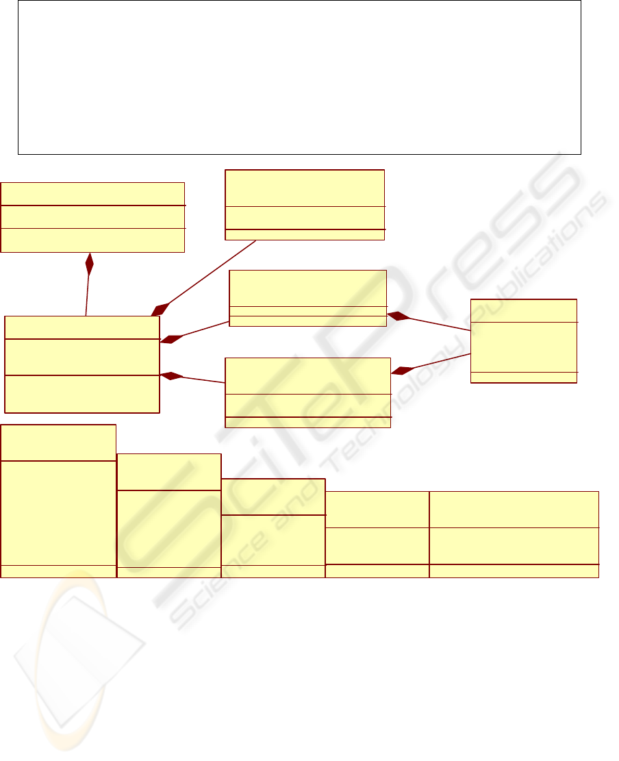
Figure 1: Architecture of UDeploy.
ICSOFT 2010 - 5th International Conference on Software and Data Technologies
104

Figure 2: Strategy modelling.
4 STRATEGY MODELLING
4.1 Architecture
The deployment strategies guide the creation of the
deployment plan. The deployment strategies allow
expressing the actions to be led to deploy a
component by assuring success and safety
properties.
The architecture presented in Figure 2 shows the
different activities to develop deployment strategies.
These activities include the creation of strategies,
their analysis, the use of predefined strategies, their
refinement and their backup.
4.1.1 Creation of Strategies
The creation of deployment strategies are expressed
in strict accordance with the terms used in the
application and the domain metamodels.
Deployment strategies contain one or more ECA
rules (the strategy language is described in section
6.3).
4.1.2 Analysis of Strategies
Once created, the strategies are passed to the
strategy analyzer, which validates or invalidates the
syntax.
4.1.3 Use of Predefined Strategies
Predefined strategies for specific technologies such
as EJB, CCM, .NET are stored in the policy
repository.
4.1.4 Refinement of Strategies
Once the ECA rules and predefined strategies have
been retrieved, the final deployment strategies need
to be refined. As there may be multiple constraints
to be added to the strategies, they must first be
checked against each other to avoid a logical
contraction in the resulting action (Davy et al.,
2006).
4.1.5 Backup strategies
Once a deployment strategy is validated, it is stored
in the policy repository.
4.2 Taxonomy and Typology of
Deployment Strategies
Deployment strategies guide creating the
deployment plan. A good deployment strategy
should express the technical choices and the
corporate policies:
Technical Choices express the influence of both
hardware and software architecture on the software
lifecycle.
Corporate Policies are specific to each
organization; they allow organizations to customize
deployment.
4.3 Strategy Language
Deployment strategies are defined in accordance
with the ECA rules (Papamarkos et al., 2003): ON
Event IF Condition THEN Action. It contains one or
MODEL-DRIVEN DEPLOYMENT OF DISTRIBUTED COMPONENTS-BASED SOFTWARE
105
Algorithm 1: Refinement of strategies.
Inputs (ECA
_
rules; Predefined
_
strategies)
Outputs (Strategies)
For every ECA_rule selected from Predefined_strategies
Add ECA_Rule to the list of Strategies
For every ECA_rule selected from ECA_rules
If ECA_rule AND Predefined_strategies is a Logical Contradiction
Then the Strategies will never be satisfied and the algorithm is
aborted
Else Add ECA_Rule to the list of Strategies
Return Strategies
DeploymentStrategies
+Configuration: String
Condition
<<IF>>
ECA_Rule
+id: String
+TypeofRule: Type
Ev e nt
<<ON>>
+DeploymentState: Command
Action
<<THEN SELECT>>
+Mode: Mode
1..*
0..1
0..1
1
Type
<<enumeration>>
+MANDATORY
+DEFAULT
Command
<<enumeration>>
+INSTALL
+UNINSTALL
+UPDATE
+ACTIVATE
+DESACTIVE
+ADAPT
+ANY
LogicalOpBetweenSelection
<<enumeration>>
+AND
+OR
CompareOp
<<enumeration>>
+=
+>
+<
+>=
+<=
MODE
<<enumeration>>
+RA
+ROIN
+OR
Selection
+AttributeName
+CompareOp
+AttributeValue
1..*
1..*
Figure 3: Strategy language.
more ECA rules.
Two kinds of rules exist: Mandatory and
Default rules. The rules apply to the association of
the couple components-sites. The results obtained
must satisfy the constraints defined by a deploy rule.
- Mandatory rules: the specified components must
be deployed on the specified sites.
- Default rules: the components and the sites
specified by their attributes apply if these
components and sites exist; if not the rule has no
effect. They are only used by default and if they do
not conflict with the mandatory rules.
Event specifies the signal that triggers the
invocation of the rule.
Condition is a logical test which, if satisfied or
evaluated to true, causes the action to be carried out.
Action is a selection of specific properties when
condition is satisfied.
Selection (AttributeName, CompareOp,
AttributeValue) may specify the properties defined
in the application model for the component part and
in the domain model for the site part.
For the mode part we rely on work developed by
(Parrish et al., 2001) according to the component
version compatibility defines in the application des-
ICSOFT 2010 - 5th International Conference on Software and Data Technologies
106

<DeploymentStrategies Configuration =”EJB profile”>
<ECA_rule TypeofRule=”MANDATORY”>
ON
<Event>
<Command>INSTALL</Command>
</Event>
IF
<Condition>
<Selection>
<AttributeName>Component.Assembly.type</AttributeName>
<CompareOp>=</CompareOp>
<AttributeValue>Business Assembly</AttributeValue>
</Selection>
AND
<Selection>
<AttributeName>Component.Implementation.Type</AttributeName>
<CompareOp>=</CompareOp>
<AttributeValue>EJB Entity</AttributeValue>
</Selection>
</Condition>
THEN SELECT
<Action Mode=”RA”>
<Selection>
<AttributeName>Site.ProvideResource.Type</AttributeName>
<CompareOp>=</CompareOp>
<AttributeValue>JEE SERVER</AttributeValue>
</Selection>
AND
<Selection>
<AttributeName>Site.ProvideResource.Type</AttributeName>
<CompareOp>=</CompareOp>
<AttributeValue>DB SERVER</AttributeValue>
</Selection>
</Action>
</ECA_rule>
<ECA_rule TypeofRule=”DEFAULT”>
</ECA_rule>
…
</DeploymentStrategies>
criptor:
– RA: Replace Always
– Replace Only If Newer (ROIN):
– Never Replace (NR): do not replace component
if already deployed
4.4 Example of Strategy
The following example illustrates the representation
of a deployment strategy: EJB Strategy.
5 UDEPLOY ENGINE CORE
5.1 Computing Plan (Creation of
Deployment Plan)
The kick off of the planning activity can be external
to the system (push) or internal to the system (pull).
In the (push) model, the system administrator
decides to trigger the schedule. To do this, the
administrator provides the application descriptor and
the domain descriptor to the planner. In the (pull)
model, it is a failure on a target node that triggers the
planning activity. Consequently, the failed node is
identified and all the components that were deployed
are listed. All the listed components from a single
application are grouped and described with a unique
application descriptor. Each application descriptor is
then provided to the planner.
The deployment plan for an application A
consists of components C1 to Ci where i>= 1 and for
a domain D consisting of Sites S1 ti Sj where j> = 1
is all valid placements (Ci, Sj). It is calculated from
a planner engine. This engine operates on a static
process which allows visualizing a state of the
system and the information remains motionless
during the computing plan or following a dynamic
process which allows visualizing the forecasts and to
supervise their realization; the information used is
variable during the computing plan. The planner
MODEL-DRIVEN DEPLOYMENT OF DISTRIBUTED COMPONENTS-BASED SOFTWARE
107

Figure 4: Computing plan.
Algorithm 2: Planner for installation (Push).
Inputs (Strategy
_
model; Application
_
model; Domain
_
model; type=”Push”)
Outputs (Deployment_Plan)
List Events defined in Strategy_model and Event.Type= “Install”
List Conditions defined in Strategy_model
List Actions defined in Strategy_model
List Component defined in Application_model
List Sites defined in Domain_model
For every Component select validConditions
For every Condition selected from ValidConditions
execute Mandatory Action for provide validSites
add ValidSites to the list of AllValidSites
/*AllValidSites={(site1,site2,site3,site4),(site1,site4),(site1,
site4,site5,site6),(site2, site4)}*/
Create new list of ValidSites which verify all Conditions
/*ValidSites={site1,site4}*/
execute Default Action for provide minimal validSites
For each Site selected from validSites
add placement (Component, Site) to the list of Placements
and make the advance reservation on Domain
add the resulting list of Placements to the Deployment_plan
Return Deployment_plan
provides a graphical interface that is only at the PIM
(platform independent model) level. Thus, it
performs the calculations of inter-component
dependencies and verifies software and hardware
needs (define by strategy model).
Once the calculation ends, i.e. all constraints are
satisfied, the planner generates a deployment plan
independent of the hardware architecture and the
technology of the application to be deployed. The
deployment plan contains all data needed to perform
the deployment properly.
Our planner provides two deployment algorithms
based on the dynamic model: a planner in Push
mode (algorithm 2) and the other in Pull mode
(algorithm 3).
ICSOFT 2010 - 5th International Conference on Software and Data Technologies
108

Algorithm 3: Planner for installation (Pull).
Inputs (Strategy
_
model; Application
_
model; Domain
_
model; type=”Pull”)
Outputs (Deployment_Plan)
List Events defined in Strategy_model and Event.Type= “Install”
List Conditions defined in Strategy_model
List Actions defined in Strategy_model
List Component defined in Application_model
List Sites defined in Domain_model
For every Site select validConditions
For every Condition selected from ValidConditions
execute Mandatory Action for provide validComponents
add ValidComponents to the list of AllValidComponents
/*AllValidComponents={(c1,c2,c3),(c1,c2,c4),(c1,c2, c3)}*/
Create new list of ValidComponents which verify all Conditions
/*ValidComponents={c1,c2}*/
execute Default Action for provide minimal validComponents
For each Component selected from validComponents
add placement (Component, Site) to the list of Placements
and make the advance reservation on Domain
add the resulting list of Placements to the Deployment_plan
Return Deployment_plan
5.2 Personalization
The deployment descriptor is an instantiation of the
deployment plan for a specific platform. It is
generally an XML file. At PIM level, we can
manipulate the concepts (component, site, resource,
constraint, dependency, and placement) and create
the instances. The persistence is processed under
Java for practical reasons. When the Java classes
were instanced, we use this data to generate the
deployment descriptor. However, the deployment
descriptor generated is conformed to specific
formalism. To assure the correspondence, we use
JDOM for the transcription of Java object in XML.
The deployment descriptor is not executed by
our framework UDeploy but by the target
middleware (Sofa runtime for SOFA profile and
StarCCM or OpenCCM for CCM profile).
5.3 Deployment Plan Execution
The components models as Fractal, EJB and COM+
do not offer a deployment descriptor which can be
executed afterward. Therefore, the calculus of the
deployment plan for this component model will be
executed by UDeploy_Executor. The execution of
the plan corresponds to: the starting up of servers,
the load of components in servers and the establish-
ment of the connections.
6 PERSPECTIVE
AND CONCLUSIONS
Deployment becomes complex, particularly when
deploying large systems on huge infrastructures. On
the one hand, solutions for deploying monolithic or
component-based systems are developed in ad hoc
manner, i.e. they are multiple. On the other hand, the
approaches used are technology-dependent. In recent
years, there have been many development projects
by academic works focusing on a new generation of
systems. These approaches enhance technology
transition. They have shown the potential of using a
model-driven approach such as MDA. The defined
models are based on expressive and simple
abstractions, so the application, the location, the
deployment process and its orchestration can be built
on top of that common foundation. We hope that the
deployment framework we present is a valuable
contribution to this new generation of systems.
REFERENCES
Alliance, O. (2005). OSGi 4.0 release. Specification avai-
MODEL-DRIVEN DEPLOYMENT OF DISTRIBUTED COMPONENTS-BASED SOFTWARE
109

lable at http://www.osgi.org/.
Bures, T., Hnetynka, P., and Plasil, F. (2006). Sofa 2.0:
Balancing advanced features in a hierarchical
component model. In SERA, pages 40–48. IEEE
Computer Society.
Clements, P. C. (1996). A survey of architecture
description languages. In IWSSD ’96: Proceedings of
the 8th International Workshop on Software
Specification and Design, page 16, Washington, DC,
USA. IEEE Computer Society.
Davy, S., Jennings, B., and Strassner, J. (2006). Policy
conflict prevention via model-driven policy
refinement. In in Proc 17th IFIP/IEEE Distributed
Systems: Operations and Management (DSOM, pages
209–220. Springer-Verlag.
Dibo, M. and Belkhatir, N. (2009). Challenges and
perspectives in the deployment of distributed
components-based software. In ICEIS(3), pages 403–
406.
Dibo, M. and Belkhatir, N. (2010). Defining an unified
meta modeling architecture for deployment of
distributed components-based software applications.
Dochez, J. (2009). Jsr 88: Java enterprise edition 5
deployment api specification. Available at
http://jcp.org/aboutJava/communityprocess/mrel/jsr08
8/index.html.
Edwards, G. T., Deng, G., Schmidt, D. C., Gokhale, A. S.,
and Natarajan, B. (2004). Model-driven configuration
and deployment of component middleware
publish/subscribe services. In GPCE, pages 337–360.
Gustavo, A., Fabio, C., Harumi, K., and Vijay, M. (2004).
Web Services: Concepts, Architecture and
Applications.
Kaur, K. and Singh, H. (2009). Evaluating an evolving
software component: case of internal design.
SIGSOFT Softw. Eng. Notes, 34(4):1–4.
Medvidovic, N. and Taylor, R. N. (2000). A classification
and comparison framework for software architecture
description languages. IEEE Trans. Softw. Eng.,
26(1):70–93.
OMG (2006a). Corba component model 4.0. Specification
available at http://www.omg.org/docs/formal/06-04-
01.pdf.
OMG (2006b). Deployment and configuration of
component-based distributed application. Specification
available at http://www.omg.org.
OMG, T. O. M. G. (2005). Omg model driven
architecture. Available at http://www.omg.org.
OMG, T. O. M. G. (2007). Unified modeling language.
Available at http://www.omg.org.
Papamarkos, G., Poulovassilis, A., Poulovassilis, R., and
Wood, P. T. (2003). Event-condition-action rule
languages for the semantic web. pages 309–327.
Parrish, A., Dixon, B., and Cordes, D. (2001). A
conceptual foundation for component-based software
deployment. J. Syst. Softw., 57(3):193–200.
Szyperski, C., Gruntz, D., and Murer, S. (2002).
Component Software: Beyond Object-Oriented
Programming. Addison-Wesley Professional. 2nd
Edition, England.
Troelsen, A. (2008a). Chapter 1: The Philosophy of .NET,
volume Pro VB 2008 and the .NET 3.5 Platform.
APress.
Troelsen, A. (2008b). Chapter 15: Introducing .NET
Assemblies, volume Pro VB 2008 and the .NET 3.5
Platform. APress.
ICSOFT 2010 - 5th International Conference on Software and Data Technologies
110
