
SEAMLESS SOFTWARE DEVELOPMENT FOR SYSTEMS
BASED ON BAYESIAN NETWORKS
An Agricultural Pest Control System Example
Isabel María del Águila, José del Sagrado, Samuel Túnez and Francisco Javier Orellana
Department of Languages and Computation, University of Almería, Spain
Keywords: Software Process Model, Decision Support System, Bayesian Networks.
Abstract: This work presents a specific solution for the development of software systems that embed functionalities
based and not based on knowledge, concerning the decision support process and the information
management processes, respectively. When constructing a knowledge model, the processes to be performed
are mainly focus on the description of the steps necessary to build it. Usually, all approaches concentrate on
adapting the software engineering lifecycle to develop a knowledge model and forget the problem of
integrating it in the final software system. We propose a process model that allows developing software
systems that use a Bayesian network as knowledge model. In order to show how to apply our software
process model, we have included a partial view of the development process of a knowledge-based system,
related to decision making in an agricultural domain, specifically with pest control in a given crop.
1 INTRODUCTION
There is not a successful method that can solve the
development of software systems that integrate
software components based and not based on
knowledge. Several solutions have been proposed to
solve this problem partially. Some of them
customize lifecycles (Alonso et al, 2000), or propose
alternative process models (Acuña et al, 1999).
Other propose to distinguish between a system
definition at contents level, (bound to knowledge)
and a definition at a container level (bound to
software) (Gachet and Haettenschwiler, 2003), or
propose the use models integrating components
based and not based on knowledge (Águila et al,
2006). But all of them are descriptive proposals that
should be developed in detail.
On the other hand, the development of
knowledge-based systems (KBS) is a modelling
activity which requires a methodology that ensures
well-defined knowledge-models that are able to
manage the complexity of the symbol-level in the
construction process (Studer et al, 1998). Bayesian
networks (Pearl, 1988; Cowell et al, 1999; Jensen
and Nielsen, 2007; Kjaerulff and Madsen, 2008) can
be used as knowledge-models to represent expert
knowledge on an uncertain domain. Several authors
have defined the process of constructing Bayesian
networks (BNs) focusing on the steps to build the
knowledge model (Laskey and Mahoney, 2002;
Korb and Nicholson, 2003). But this works only
adapt the software engineering lifecycle to the
development of BNs models and forgets the problem
of integrating them in the final software system.
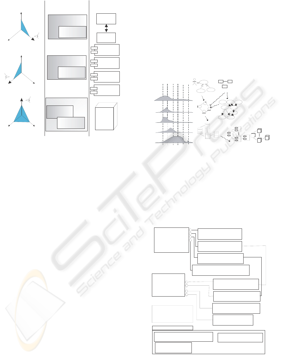
Figure 1 shows the vision of a software
development project from the points of view of a
customer, a software engineer and a knowledge
engineer. The knowledge engineer (Fig. 1A) makes
use of knowledge engineering to define what is
needed to be done (tasks) to build the software
product, relegating to the background the tasks
defined by software engineering. The software
product that results is a KBS. The software engineer
(Fig. 1B) applies its skills, tools and software
engineering methods to develop a software product
(system), where the knowledge is only another
element. Finally (Fig. 1C), the customer focuses on
quality and the need of cooperation between
engineerings (Juristo and Acuña, 2002; Aguila et al.
2006; Studer et al., 1998) so that the final software
properly covers all her/his needs. Thus, software
components based and not based on knowledge must
be integrated homogeneously. The lack of
cooperation leads to a useless software product.
456
del Águila I., del Sagrado J., Túnez S. and Orellana F. (2010).
SEAMLESS SOFTWARE DEVELOPMENT FOR SYSTEMS BASED ON BAYESIAN NETWORKS - An Agricultural Pest Control System Example.
In Proceedings of the 5th International Conference on Software and Data Technologies, pages 456-461
DOI: 10.5220/0003007904560461
Copyright
c
SciTePress
Effort
Who Define
s
Rules
Software
Product
Client
Knowledge
engineer
Software
engineer
Knowledge
engineering
Software
engineering
Client
Knowledge
engineer
Software
engineer
(A)
(B)
processing
decision
making
report
generation
users
management
Knowledge
engineering
Software
engineering
Client
Knowledge
engineer
Software
engineer
Quality
(C)
End user’s
Software
System
Knowledge
engineering
Software
engineering
Inference
Engine
Bayesian
Network
Figure 1: Views of the software development process.
In this paper we define a process model that
allows the development of software systems in
which BNs are used as the knowledge-based part of
the system. Our goal is to define the tasks in order to
manage the development of a software project which
in turn includes the development of a knowledge
model which, in our case, is a BN.
This paper is organized in three sections. Section
2 describes how to integrate the tasks for modelling
knowledge in the software development project,
defining our process model. Section 3, we have
included a partial view of a KBS system
development for decision making in agricultural pest
control domain, as an application to a real world.
Finally, conclusions are given in Section 4.
2 BN CONSTRUCTION IN THE
SOFTWARE PROCESS
A software project has as goal to manage and
translate the user needs into software. In order to do
that, developers need to apply a methodological
development approach following a well-defined
process model, starting from business modelling and
ending with the delivery of the software product. A
software process model is a complete and well-
defined set of activities required for converting user
needs into a set of consistent artefacts making up a
software product (Juristo and Acuña, 2002).
Our software process model integrates
knowledge modelling as a workflow. Our goal is to
construct, as homogeneously as possible, a software
product in which a knowledge model is integrated as
any other client needs. This is achieved through the
execution of workflows. Our model has six
workflows (Figure 2): Requirement Modelling
(RM), Expert Modelling (EM), Specification of the
Software Solution (SSS), Design of the Software
Solution (DSS) Coding and Debugging (CD), and
Software Evaluation (SE). These workflows are
broken down in activities (Figure 3).
Figure 2: The process model proposed.
Requirement modelling (RM) characterizes the
client’s needs and the organisational context in
which the software system has to operate. Working
with requirements is a critical and complex process.
The system scope has to be clearly identified,
considering any benefit or impact of the software
solution on the whole organisation, in terms of
processes and domain concepts.
Figure 3: The process model proposed.
Expert Modelling (EM) is related to the artificial
intelligence techniques applied in order to build the
RM
Iterations
EM
DSS
CD
Use case model
Domain model
Analysis model
Design model
Implementation models
SSS
Bayesian Nets
W
o
r
k
f
l
o
w
s
A
r
t
e
f
a
c
t
s
<<workflow>>
RM
Requirement
Modelling
<<workflow>>
EM
Expert
Modelling
<<workflow>> DSS
Design of the Software Solution
<<workflow>> CD
Coding and Debugging
<<workflow>> SE
Software Evolution
P
L
A
T
F
O
R
M
D
E
P
E
N
D
E
N
T
W
O
R
K
F
L
O
W
S
<<activity>> PI
Process Identification
<<activity>> PF
Problem Formulation
<<activity>> DPS
Definition of Project Scope
<<activity>> DI
Domain Identification
<<activity>> QS
Qualitative Structuring
<<activity>> VD
Variable Definition
<<activity>> VT
Validation Testing
<<activity>> QE
Quantitative Elicitation
Help in
Help in
<<workflow>> SSS
Specification of the
Software Solution
SEAMLESS SOFTWARE DEVELOPMENT FOR SYSTEMS BASED ON BAYESIAN NETWORKS - An Agricultural
Pest Control System Example
457

knowledge model. The methods used are interaction
with experts (e.g. interviews) and ‘learning’ from
databases when they are available. We focus on
modelling knowledge as a BN, but our process
model can be easily modified to integrate any other
knowledge model (rules, neural networks,...) by
redefining the activities needed for the specific type
of knowledge model (Águila et al, 2006).
EM and Specification of the Software Solution
(SSS) model the software in an implementational
independent level. While EM focuses on knowledge,
SSS focuses on requirements defining the set of
functionalities. Some of these functions correspond
to the knowledge model that is being defined during
the EM. SSS activities are engaged in building a
software model in which functionalities have a
unified representation, without taking into account
whether they are based on knowledge or not.
The design of the software solution (DSS),
coding and debugging (CD), and software evolution
(SE) workflows, are dependent on the coding
language and on issues related to the hardware
platform and they are out of the scope of this paper.
Through the execution of RM, EM and SSS
workflows we can develop seamlessly a software
product that embeds a BN as knowledge model.
2.1 Requirement Modelling
A software project starts by focusing on some of the
business problems that can be improved by means of
software systems to assist the business processes of
the organization. The RM workflow is more than
just a specification of future functionalities of the
system. It extends the “what the system must do“
approach to “why the system is like this” (Rolland
and Prakash, 2000). If the improvements identified
involve a non-software solution (e.g., an
improvement in knowledge management, worker
training tasks), then the software project is stopped.
The RM workflow is broken down into four
activities: problem formulation (PF), process
identification (PI), domain identification (DI), and
definition of project scope (DPS).
PF faces up to the description of the processes
applied to solve the problem. The benefit, cost and
impact that the software system has on the entire
organization, must be identified. Here, any
information analysis and elicitation techniques can
be applied: joint application development,
interviews and/or brainstorming.
Business processes are the set of processes
defined in an organization in order to achieve its
business goal. Each of them is characterized by a
dataset produced and manipulated by a set of
operations performed by actors. Here is where PI
fits. PI techniques are those that express what must
be done, such as functional analysis or protocol
analysis. The artefacts used can be expressed by
templates in natural language, or by diagrams (e.g.
use cases, activities, state transitions or data flows).
Each of the business processes identified during
PI manages data and information. DI activity is
related with the process of building a domain model
that describes the relevant concepts for the
organization. Those techniques related to data
modelling (e.g. glossaries, entity/relationships
diagrams, class diagrams, etc.) are applicable in DI.
DPS activity has as goal to achieve a
commitment about the project limits. With the
artefacts previously defined, we must identify what
are the business areas that can be improved by a
software solution. DPS includes the task of building
a feasibility study and the definition of a contract
that reflects the scope of the software project.
2.2 Expert Modelling using BNs
Our aim is to model knowledge using only BNs,
leaving other methodologies out of the scope of this
paper. Formally, a BN (Pearl, 1988; Cowell et al,
1999; Jensen and Nielsen, 2007; Kjaerulff and
Madsen, 2008) is a pair (G, P), where G =(U, A) is a
directed acyclic graph (DAG), where the set of
nodes U = {V
1
, V
2
, …, V
n
} (i.e. the variables), and
the set of directed edges (or arcs) A is the set of
direct dependence relations between variables. P is a
joint probability distribution over U, given by:
,
,…,
∏
,
where the condi-
tional probability of each variable V
i
in U given its
set of parents, pa(V
i
), in the DAG is P(V
i
|pa(V
i
)).
Research on BNs research was initially focused
on inference algorithms. Next research attention
shifted to the difficulties of finding domain experts
willing to share their knowledge and enter it in a
software system. This developed into automated
learning methods. Nonetheless, what is needed from
a practical point of view is a methodology (Laskey
and S. M. Mahoney, 2000; Korb and Nicholson,
2003) enabling the construction of BNs.
A BN has qualitative and quantitative
components: a DAG and a set of conditional
probability distributions. Thus, the EM workflow for
BNs comprises four activities: variable definition
(VD), qualitative structuring (QS), quantitative
elicitation (QE), validation and testing (VT).
Normally, the process of building such a BN
model is perceived by the expert as a tedious and
ICSOFT 2010 - 5th International Conference on Software and Data Technologies
458

time consuming effort. So it is desirable to get an
early commitment between the expert and the
engineer in order for them to have time enough to
learn. The expert has to know what knowledge
models are and what they can do, whilst the engineer
must learn about the domain. Such aspects must
have been previously tackled during RM in DI and
PI activities. Once it is decided that BN modelling is
plausible, the results obtained during PF and DI, can
be used to identify variables. During VD hypothesis
events, are detected and grouped into sets of
mutually exclusive and exhaustive events to form
hypothesis variables. Achievable information
relevant to the hypothesis must also be collected.
Then these pieces of information are grouped into
information variables.
QS is in charge of representing relations between
variables under the form of a DAG. A link
represents dependence or influence between
variables. The most usual techniques for modelling a
BN based on its structure are undirected
dependence, parent divorcing and functional
dependence (Jensen and Nielsen, 2007; Kjaerulff
and Madsen, 2008; Korb and Nicholson, 2003). QE
must acquire the conditional probability distributions
P(Vi|pa(Vi)) (Jensen and Nielsen, 2007; Kjaerulff
and Madsen, 2008). QS and QE are activities
intrinsically related, because the greater the number
of parents of a variable, the greater the complexity
of its associated conditional probability distribution.
In those cases in which there are enough data
available, machine learning techniques can be used
in QS and QE (Neapolitan, 2004).
Finally, VT activity checks that the BN model
meets specifications and that it fulfils its intended
purpose. Validation can be expressed by ‘Are you
building the right BN model?’ and testing by ‘Are
you building the BN model right?’
2.3 Specification of the Software
Solution
This workflow is similar to the analysis task in the
development of software that is not based on
knowledge. The result is a model described in
developer language that provides a conceptual view
of the software system. Requirements must be
refined as software functionalities, removing
inconsistencies, and taking into account that some of
these functionalities are related to the inference tasks
carried out by the BN model developed in EM.
Any of the modelling languages used in software
development may be used to describe this model. If
an object-oriented approach is applied, the interface,
entity, control, (Jacobson et al, 1992) and knowledge
(Águila et al, 2006) stereotype classes can be used.
An interface class models interactions between
software system and actors. An entity class models
long-term data or data persistent in the software
system. A control class represents a use case or
process coordination, calculations or controls. A
knowledge class represents the inference tasks. The
specification of the software solution implies
thinking about the structure of the system and must
serve also as a good starting point when dealing with
its design. This modelling activity entails allocating
the system behaviour in different object classes.
3 CASE STUDY
This section shows how to apply our software
process model, giving a simplified description RM,
EM, SSS workflows. We want to emphasize the
collection of products that will be generated.
Our case is related to pest control in a given crop
under the regulation of Integrated Production
Quality standard (Águila et al, 2003). This standard
is adopted by a group of growers in order to achieve
a quality production certification. It involves
intervention by technicians, marketing controls, and
periodical inspection by the certification agencies.
Software project development starts with RM.
The first activity consists of collecting, structuring
and organizing all the relevant data for a concise and
accurate definition of the problem to be solved by
the software system (problem formulation–PF).
Integrated production involves handling and storing
a huge amount of information, and making decisions
about all actions performed to fulfil the quality
regulations. During PF, all of the business actors
were interviewed and we identified the major
improvements that could be achieved by applying
new technologies. As result, we found that in an
integrated production system, decisions are made at
two levels. First, a decision is made on whether crop
control action is necessary by sampling pests and
estimating risk of attack. Then if it is decided that
crop control action is required, the product
(chemical or biological) to be applied has to be
selected. The treatment advised has to respect
natural enemies.
PI is done at the same time as PF. This activity
generates a model of the processes identified which,
in this case, are represented as use cases. The typical
processes in an integrated production problem are
shown in Figure 4. All tasks related to pest control
are performed by growers and agronomists in the
SEAMLESS SOFTWARE DEVELOPMENT FOR SYSTEMS BASED ON BAYESIAN NETWORKS - An Agricultural
Pest Control System Example
459
Monitor crop process. Use cases, Market Produce,
Act in Crop, Certify Crop Quality, and Finish
Growing Season, are out of scope because they are
all related to information required for quality
management standards. DI models the data used in
the processes. In the case, a crop is a complex
system consisting of a plot of land, plants, a set of
diseases and pests, and natural enemies that may be
able to control them. The problem is to decide what
treatment to apply, in order to maintain a balanced
system. Figure 5, shows the diagram obtained as
result of DI activity.
Figure 4: Processes in an Integrated Production system.
DPS is concerned with achieving a commitment
that has to take the form of a contract. In this project
our attention is focused on all the pest control
processes performed in Monitor Crop. This use case
can be described as the following informal scenario:
“Each week, the agronomist samples the crop’s
condition and makes an estimation of the risk of pest
attack. Crop sampling consists of direct observation
and count of harmful agents in randomly selected
plants. Where imbalance is detected, the agronomist
advises a treatment.”
As result of the RM a set of requirements and
domain concepts have been defined. The scope of
the project has been limited to estimating the risk of
pest attack in grapes omitting the process of
choosing a control action.
Figure 5: Domain identified.
The next workflow is EM and its first activity
concerns to select the set of relevant variables. One
of the benefits of our development approach is that
the results found in the previous workflow RM, are
reused during EM and help to reduce knowledge
modelling effort. More precisely, DI activity helps in
VD by identifying the main concepts to be
considered for inclusion in the BN, whereas PI
activity helps to identify relations between variables
that can be used when defining the QS of the BN.
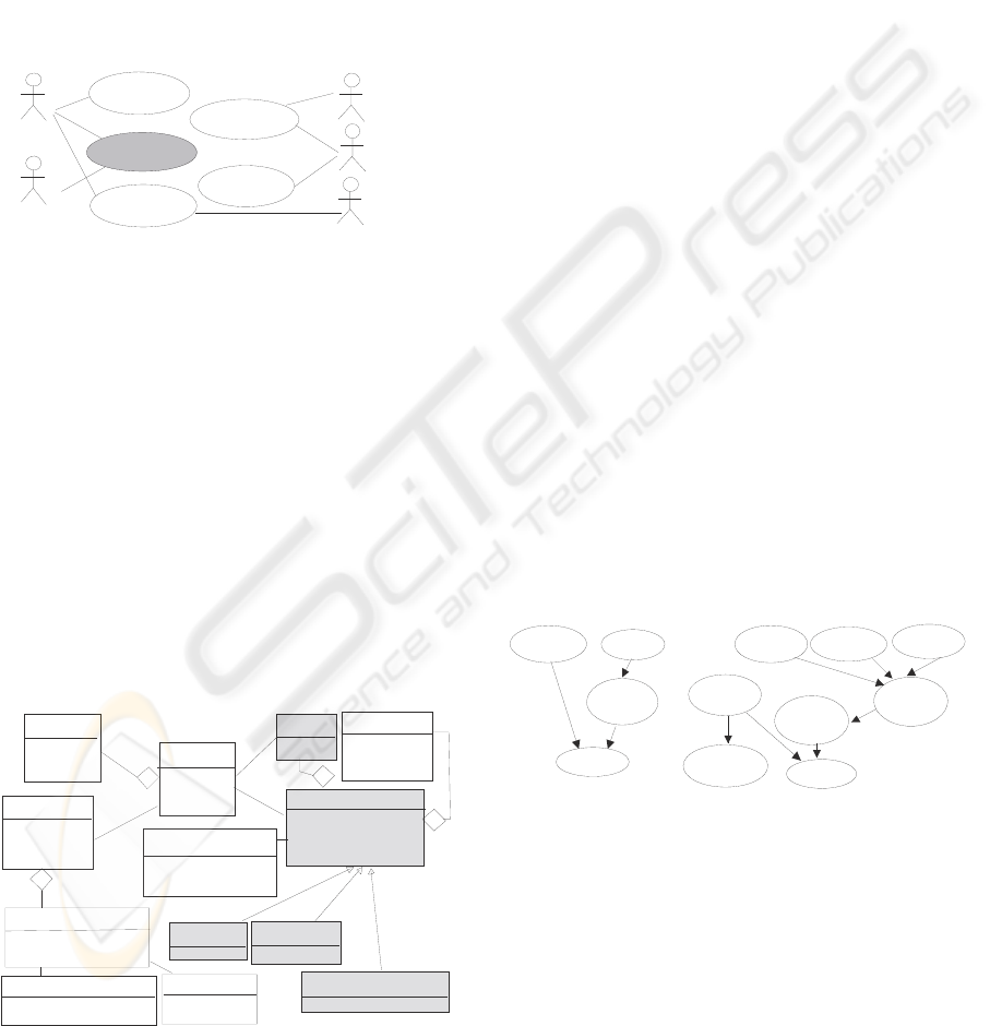
Within the scope of integrated production
systems, the knowledge domain is shown shaded in
Figure 5. When an agricultural expert visits a
greenhouse, he writes down the date of the visit and
samples the crop, including information about fauna,
weather (wind, rain, etc.) and environment (weeds).
For each crop-harmful agent pair, we need only
to consider an instantiation of the knowledge domain
model represented. The general schema for a crop-
harmful agent pair consists of observing the crop’s
condition and fauna. Crop condition is measured in
terms of its phenology. The presence of fauna is
important to estimate the intensity of the attack. The
crop condition, along with the intensity of pest
attack, determines the need for applying a plant
health treatment or not. Figure 6(a) shows the
general BN structure elicited from the knowledge of
the domain expert, whilst Figure 6(b) illustrates its
application to the grape flea. Once the BN structure
has been established, the probabilities are estimated
(QE) based on a database of cases, completing the
construction of the BN model. This expert modelling
process has been successfully applied to determine
the need of applying a treatment for the olive’s fly
(dacus olae) (Sagrado and Águila, 2007).
Figure 6: BN for Integrated Production Systems.
The SSS workflow produces the software model
that has to be designed, coded and debugged. The
model produced can be represented using the class
stereotypes. A partial view of this model is shown in
Figure 7. Action begins when an actor calls up a use
case by sending a message to the system. In this case
we begin with a new visit message. The agronomists
interact with the system by entering a new visit and
Grower
Quality
technicians
Stockholder
Governement
agricultural
technicians
Agronomist
act in crop
monitor crop
market
produce
certifiy crop
quality
finish
growing
VISIT
PLOT
PLANT
Make
Plant with
GROWER
COOPERATIVE
Name
Adress
Phone …
Code
Adress
Location
Area
Features
Va r i e ty
Initial Date
Date
Belonges to
EXPERT
Name
Phone...
STOCKHOLDER
Adress
Capacity
OB SE RVAT I ON
Date
Name
Plant observed
Va l ue
ACTION
Type
Product
Doses ....
INSPECTION
Date
Who
Result
FAUNA
Va l ue
CLIMATE
Va lu e
ENVIRONMENT
Va lue
Fauna
Winged
forms?
Predators?
Parasites?
Crop
condition
Fauna
condition
Crop
condition
Attack
intensity
Treat?
Days until
harvest
Attack
intensity
(a) DAG for a general
Integrated Production system
(b) A BN structure for the
grape’s fly case
Treat?
ICSOFT 2010 - 5th International Conference on Software and Data Technologies
460

some sample data, and get a therapeutic action plan
as the result. This interaction is done through the
interface, visit, sampling template and therapeutic
plan classes. The toss class performs the calculations
necessary for selecting which plants a sample should
be taken from. The estimate pest risk and treat pest
classes make the inference. The information
obtained is sent to the user by interface classes.
Agronomis
t
sampling
template
plot
toss
observation
estimate
pest risk
therapeutic
plan
visit
1: new visit
2: show data
3: Parameters
idenfification
4: new
observation
5:record
sampling
6:record
observation
14: show plan
8: show pest
to be controled
9: select
treatment
10: fix
treatment
action
7: pest
incidence
analysis
treat
pest
Figure 7: Partial view of a class diagram.
4 CONCLUSIONS
This work shows how to integrate methods of
software and knowledge engineering into a unified
perspective in which components, independently if
they are based on knowledge or not, are integrated in
shaping the software system for the end user. We
have chosen BNs as technique to handle uncertainty
in decision-making problems due to the non-
existence of a software development process for
systems that used them as knowledge model. Our
process model allows the seamless inclusion of BNs
into a final software solution for an organizational
environment. The applicability of our solution has
been tested in a real world problem: integrated
production in agriculture.
In future works, it would be of interest to test the
applicability of our approach to other real cases and
attempt to adapt the EM to other knowledge
modelling techniques in order to verify that we will
substantially reduce the software development effort
required, including the study of the horizontal
dimension of the project (time and iterations).
ACKNOWLEDGEMENTS
This research work was supported by the Spanish
Ministry of Education (TIN2007-67418-C03-02)
and by the Junta of Andalucía (P06-TIC-02411.02).
REFERENCES
Acuña, S. T., López, M., Juristo, N., Moreno, A. M., 1999.
Process model applicable to software engineering and
knowledge engineering. Int. Jour. of Soft. Eng. and
Knowl. Eng., 9 (5), 663–687.
Águila, I. M., Cañadas, J., Bosch, A. Túnez, S. Marín, R,
2003. Knowledge model of therapy administration
task applied to an agricultural domain. In KES 2003
7th Int. Conf., LNAI 2774, Springer, 1277–1283.
Águila, I. M., Cañadas, J., Palma, J. Túnez, S. 2006.
Towards a Methodology for Hybrid Systems Software
Development. In SEKE 2006 18th Int. Conf. on Soft.
Eng. and Knowl. Eng., 188-195.
Alonso, F., Fuentes, J. L., Martìnez, L., Montes, C., 2000.
An incremental solution for developing knowledge-
based software: its application to an expert system for
isokinetics interpretations. Experts Systems with
Applications, 18 (3), 165-184.
Cowell, R. G., Dawid, A., Lauritzen, S. L., Spiegelhalter,
D. J., 1999. Probabilistic networks and experts
systems, Springer-Verlag, New York.
Gachet, A., Haettenschwiler, P., 2003. Developing
Intelligent. Decision Support Systems: A Bipartite
Approach. LNAI, 2774, 87–93.
Jacobson, I., Christerson, M., Jonsson, P., Övergaard, G.,
1992. Object-oriented Software Engineering: A Use
Case Driven Approach. Addison-Wesley Professional.
Jensen, F. V., Nielsen, T., 2007. Bayesian networks and
decision graphs, Springer-Verlag, New York.
Juristo, N., Acuña, S.T., 2002. Software Engineering and
Knowledge Engineering. Expert Systems with
Applications, 23 (4), Elsevier, 345-347.
Kjaerulff, U. B., Madsen, A. L., 2008. Bayesian networks
and influence diagrams: a guide to construction and
analysis, Springer-Verlag, New York.
Korb, K. B., Nicholson, A.E., 2003. Bayesian Artificial
Intelligence, Chapman & Hall.
Laskey, K. B., Mahoney, S. M., 2000. Network
Engineering for Agile Belief Network Models, IEEE
Trans. on Know. and Data Eng., 12 (4), 487-498.
Neapolitan, R. E., 2004. Learning Bayesian Networks.
Prentice Hall, Upper Saddle River, NJ.
Pearl, J., 1988. Probabilistic reasoning in intelligent
systems: networks of plausible inference. Morgan
Kaufman, San Mateo, CA.
Rolland, C., Prakash, N., 2000. From conceptual
modelling to requirements engineering. Annals of
Software Engineering 10 (1-4), 151-176.
Sagrado, J., Águila, I. M., 2007. Olive Fly Infestation
Prediction Using Machine Learning Techniques.
LNCS 4788, Springer, 229-238.
Studer, R., Benjamins, R., Fensel, D., 1998. Knowledge
engineering: Principles and methods. Data &
Knowledge Engineering, 25 (1-2) .Elsevier, 161-197.
SEAMLESS SOFTWARE DEVELOPMENT FOR SYSTEMS BASED ON BAYESIAN NETWORKS - An Agricultural
Pest Control System Example
461
