
EXTRACTING OBJECTS BY CLUSTERING OF FULL PIXEL
TRAJECTORIES
Hisato Aota, Kazuhiro Ota, Yuichi Yaguchi and Ryuichi Oka
Department of Computer and Information Systems, University of Aizu, Tsuruga, Aizu-Wakamatsu, Japan
Keywords:
Object tracking, Object segmentation, Pixel-wise matching, Motion feature.
Abstract:
We propose a novel method for the segmentation of objects and the extraction of motion features for moving
objects in video data. The method adopts an algorithm called two-dimensional continuous dynamic pro-
gramming (2DCDP) for extracting pixel-wise trajectories. A clustering algorithm is applied to a set of pixel
trajectories to determine objects each of which corresponds to a trajectory cluster. We conduct experiments
to compare our method with conventional methods such as KLT tracker and SIFT. The experiment shows that
our method is more powerful than the conventional methods.
1 INTRODUCTION
Tracking and segmentation of moving objects in
video are veryimportantfor many tasks, such as video
surveillance and event inference. Humans are the
principal actors in daily activities, or locomotion (e.g.,
walking, running and standing), and so human mo-
tion is a key class within the field of computer vision.
Many approaches for object tracking and segmenta-
tion have been proposed. These differ from each other
primarily in the way they approach the problem. Ap-
proaches depend on such aspects as the target objects,
context and environment in which tracking is per-
formed and the end use for which tracking informa-
tion is being sought. Yilmaz(Yilmaz et al., 2006) de-
clared object tracking as the problem of estimating the
trajectories of objects that are moving continuously in
an image sequence from initial frame to end frame.
In addition, the estimation must maintain a consistent
division of objects in the continuous image sequence
with segmentation. It must be also able to provide ob-
ject information such as area, orientation or shape. In
previous methods, continuous trajectories can only be
generated by detecting objects, which makes it hard to
track objects from data. The difficulty of this problem
is the difficulty of fixing units of trajectories in time-
sequential images. The problem becomes even more
difficult when the movement trajectories are extracted
from the object area with inadequate region detection.
Much of the previous research concentrated on ex-
tracting objects from background areas. We felt that
an alternative method based on pixel tracking would
not be as restricted as the previous methods.
In our laboratory, we developed a method named
two-dimensional continuous dynamic programming
(2DCDP), which can define full pixel correspon-
dences between two images. By using this approach,
it became possible to extract trajectories of all the pix-
els in an initial frame in time-sequential images. Next,
to extract effective trajectory groups from these, we
used two strategies. The first is to remove the trajecto-
ries of background pixels, and the second is to cluster
the trajectories that are not removedand to group sim-
ilar trajectories. The goal of our work is to prove that
our proposed method can track and segment moving
objects without object detection or recognition, and
without pre-knowledge of the state of an object, its
motion or environmental factors such as people walk-
ing nonlinearly or complex human motions. To prove
the method’s benefits, we demonstrate an effective
full-pixel matching method and connect its outputs.
Experimental results indicate that it is possible to ex-
tract pixel trajectories of objects and segment them by
clustering trajectories.
2 RELATED WORK
Many methods for object tracking have been pro-
posed. Examples include tracking methods with pre-
knowledge of an object’s state, using Haar-like fea-
tures(VIOLA, 2001), HOG features or mean-shift
colour features using a statistical classifier (boost-
ing) detector(Mochiki and Katto, 2007) (Nakagawa
65
Aota H., Ota K., Yaguchi Y. and Oka R. (2010).
EXTRACTING OBJECTS BY CLUSTERING OF FULL PIXEL TRAJECTORIES.
In Proceedings of the International Conference on Signal Processing and Multimedia Applications, pages 65-72
Copyright
c
SciTePress

et al., 2009)(Takeuchi et al., 2009). In addition,
Mikami(Dan et al., 2009) proposed a memory-based
particle filter(M-PF), which can visually track mov-
ing objects that have complex dynamics. It provided
robustness against abrupt head movements and re-
covered quickly from tracking failure caused by oc-
clusions. Yamashita’s(Takayoshi et al., 2008) pro-
posed tracking method with a soft decision feature
(EHOG) and online real boosting improved tracking
performance in scenes with human poses and posture
changes.
Deterministic methods for point correspondence
using object tracking based on feature points define
a cost of associating each object in frame t − 1 to
a single object in frame t by using a set of mo-
tion constraints. Rabaud(V. Rabaud, S. Belongie,
2006) developed a highly parallelized version of the
KLT tracker(Shi and Tomasi, 1994) that combined
graph cuts and RANSAC clustering and was able
to count objects in crowds. Sugimura(Sugimura
et al., 2009) proposed a human tracking method
with trajectory-based clustering with a gait feature
by KLT corresponding points and Delaunay triangu-
lation. Tsuduki(Tsuduki et al., 2007)(Yuji and Hi-
ronobu, 2009) used mean-shift searching to track a
point based on the information obtained by a SIFT
(Lowe, 2004), and obtained a better tracking perfor-
mance than KLT because a SIFT feature is invariant to
changes caused by rotation, scaling, and illumination.
3 SYSTEM OVERVIEW
In this section, we describe each system for this pro-
posed method. First, 2DCDP extracts full pixel cor-
responding points between frame of t and t + 1. Then
connecting corresponding points with outputs of all
frames by 2DCDP, it generate full pixel trajectories.
Then thresholding trajectories, it divides trajectories
into two groups which is moving objects trajectories
and background trajectories. Finally, divided trajec-
tories are extracted and its of moving objects are ex-
tracted by incremental clustering (Figure1).
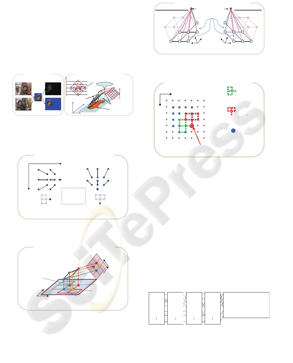
Figure 1: Proposed Work Flow.
3.1 2DCDP Algorithm
2DCDP(Yaguchi et al., 2009) is an extension of
CDP(Oka, 1998) to 2D correlation, and is an effec-
tive algorithm for full-pixel matching (Figure 3). The
pixel coordinates of the input image S and reference
image R are defined by:
S , {(i, j)|1 ≤ i ≤ I, 1 ≤ j ≤ J} (1)
R , {(m, n)|1 ≤ m ≤ M, 1 ≤ n ≤ N} (2)
The pixel value at location (i, j) of the input im-
age S
p
is S
p
(i, j) = {r, g, b}, and the pixel value
at location (m, n) of the reference image R
p
is
R
p
(m, n) = {r, g, b}, where r, g, and b are nor-
malized red, green, and blue values respectively,
and (0 ≤ { r, g, b} ≤ 1). We define the mapping
R → S, (m, n) ∈ R and (ξ(m, n), η(m, n)) ∈ S by
(m, n) =⇒ (ξ(m, n), η(m, n)), set the end location for
pixel matching as
ˆ
i = ξ(M, N),
ˆ
j = η(M, N) and
the point (
ˆ
i,
ˆ
j) as a nomination of the spotting point
that is determined at the M + N − 1th iteration of the
proposed algorithm. Next, we set the local distance
d(i, j, m, n) as the difference value between S
p
(i, j)
and R
p
(m, n), and set w(i, j, m, n) as the weighted
value of each local calculation. In this implemen-
tation, the local distance is defined as d(i, j, m, n) =
(S
p
(i, j) − R
p
(m, n))
2
, and weights are set to 1 for all
paths (Figure 5). The accumulated local minimum
D(i, j, m, n) is used to evaluate the decision sequence,
and is defined as:
D(
ˆ
i,
ˆ
j, m, n) =
1
W
min
ξ,η
{
M
∑
m=1
N
∑
n=1
w(ξ(m, n), η(m, n), m, n)
d(ξ(m, n), η(m, n), m, n)} (3)
Then ξ
∗
(m, n) and η
∗
(m, n) are used to represent the
optimal solutions in ξ(m, n) and η(m, n) respectively,
where W is the optimal accumulated weight W =
∑
m,n
w(ξ
∗
(m, n), η
∗
(m, n), m, n). To ensure continu-
ity and monotonicity, K(m, n) = {ξ(m− 1, n), η(m−
1, n)} and L(m, n) = {ξ(m, n − 1), η(m, n − 1)} are
used to define the sets of points that are movable in the
i and j directions in the input image, taken from the
movements in the m and n directions in the reference
image. The following equation defines the relation-
ship between two corresponding pixels (m− 1, n− 1)
and (m, n) (see Figure 4):
(ξ(m− 1, n − 1), η(m− 1, n− 1)) ∈
K(m, n) ⊗ L(m− 1, n) ∩ L(m, n) ⊗ K(m, n− 1) (4)
Here, the operator ⊗ represents the connection be-
tween a set of points on the left and a set of points on
the right. To calculate the accumulated local distance,
each accumulated local minimum D(i, j, m, n) is de-
rived from two previous accumulated local minima
D(i
′
, j
′
, m− 1, n) and D(i
′′
, j
′′
, m, n− 1). In this way,
we define the rank l = m + n − 1, as shown in Fig-
ure 2 (b), to calculate the accumulated local minimum
smoothly. Note that, for the accumulation and back-
tracking, 2DCDP selects two local paths to check
the connection of the four points (m, n), (m − 1, n),
(m, n− 1), and (m− 1, n − 1) that form a quadrangle
(Figure 4 ).
Spotting point
i
j
m
n
Input image
(i,j)
Reference image
(m,n)
Optimal path
Object and segmentation
area projections
Segmentation area
l
Rank
l = (m + n -1)
Rank
5
3
1
2
4
6
8 7
9
mn
1
2
3
4
5
Rank
A nod e depends on
two lower-lank nodes
Reference
image
Corresponding pixels
Segmentation area
Input images
(a) Example of full pixel matching
(b) Determination of segmented area obtained by projecting
optimal paths in the 3D space (i, j, l) on the input image
Figure 2: Full pixel matching overview. (a) An example of
full pixel matching; (b) Optimal paths are able to explain a
3D space (i, j, l) in the input image. l is the rank used in the
expression l = m+ n− 1.
+ = 䋭
-45㫦5 2
0㫦4 1 7
+45㫦6 3
4 1 7
5 2
6 3
4
1
7
6
3
5
2
Row direction Column direction
i
j
),()),1(),,1(( nmKnmnm =−− ηξ
),())1,(),1,(( nmLnmnm =−− ηξ
(a) Two direction and seven path patterns for 2DCDP
Figure 3: Two directions and seven paths for selecting opti-
mal path to accumulate value.
i
j
Input image
(i,j)
m
n
Reference image
(m,n)
)1,(),(),1(),( −⊗∩−⊗ nmKnmLnmLnmK
))1,(),1,((),( −−= nmnmnmL ηξ
)),1(),,1((),( nmnmnm −−= ηξ
)),(),,((),( nmnmji ηξ=
(b) Example explaining the roles of K(m,n) and L(m,n)
Figure 4: One case (linear matching) among the possible
cases for optimal matching of local images, which include
many different cases of nonlinear optimal matching of local
areas.
m-direction:
n-direction:
7
1
4
2
5
3
6
7
1
4
2
5
3
6
1
1
1
1
1
1
1
1 1 1
1
1
1
1
i
j
i
j
m
n
),1),,1(),,1(( nmnmnmD −−− ηξ
),),,(),,(( nmnmnmD ηξ
),( nmK
),( nmL
)1,),1,(),1,(( −−− nmnmnmD ηξ
(c) Path and weight explaining for accumulation calculation
Weight function
),),,(),,(( nmnmnmw ηξ
Figure 5: Seven-path map and weight. All weights w are set
to 1 in implementation, but this can be changed.
L(m,n):
Candidate point group
of (ξ(m,n-1), η(m,n-1))
K(m,n):
Candidate point group
of (ξ(m-1,n), η(m-1,n))
(K(m,n)⊗L(m-1,n))
∩(L(m,n)⊗K(m,n-1)):
Candidate point group of
(ξ(m-1,n-1), η(m-1,n-1))
(ξ(m,n), η(m,n))
j
i
(d) Candidate conditions for neighboring pixels
Figure 6: Each i and j direction can connect seven candidate
pixels as (a) and (c). 2DCDP selects the node that has a
minimal accumulation value from among these paths, but a
node has depending on only two lower-rank nodes.
3.2 Connecting Corresponding Points
To extract the trajectories of the pixels in the first
frame, we showed that frame (i
k
, j
k
) at time t and
frame (m
k
, n
k
) at time t + 1 are the points that cor-
respond by 2DCDP. Therefore, the correspondence
points in the following frame are derived for all the
pixels in the first frame, and the following frame is
processed similarly, the trajectory of the first-frame
pixels in the time sequence of images can be de-
termined. However, if both (i
a
, j
a
) and (i
b
, j
b
) at
time t correspond to (m
c
, n
c
) at time t + 1, they are
connected. As a result, the number of trajectories
decreases.(Figure7)
m
1,
n
1,
- i
1,
j
1
m2,n2, - i2,j2
m
3,
n
3,
- i
3,
j
3
m4,n4, - i4,j4
m
5,
n
5,
- i
5,
j
5
m6,n6, - i6,j6
m
k,
n
k,
- i
k,
j
k
m
1,
n
1,
- i
1,
j
1
m2,n2, - i2,j2
m
3,
n
3,
- i
3,
j
3
m4,n4, - i4,j4
m
5,
n
5,
- i
5,
j
5
m6,n6, - i6,j6
m
k,
n
k,
- i
k,
j
k
m
1,
n
1,
- i
1,
j
1
m2,n2, - i2,j2
m
3,
n
3,
- i
3,
j
3
m4,n4, - i4,j4
m
5,
n
5,
- i
5,
j
5
m6,n6, - i6,j6
m
k,
n
k,
- i
k,
j
k
m
1,
n
1,
- i
1,
j
1
m2,n2, - i2,j2
m
3,
n
3,
- i
3,
j
3
m4,n4, - i4,j4
m
5,
n
5,
- i
5,
j
5
m6,n6, - i6,j6
m
k,
n
k,
- i
k,
j
k
x1 1,y11 - x12 ,
y
12
-
x1 3,y13 - x1 4,y1 4 - x15 ,y15
x2 1,y21 - x22 ,
y
22
-
x2 3,y23 - x2 4,y2 4 - x25 ,y25
x3 1,y31
-
x3 2,
y
32 - x33 ,y33 - x44,y44 - x55,y55
x4 1,y41 - x42 ,
y
42
-
x4 3,y43 - x4 4,y4 4 - x45 ,y45
x5 1,y51 - x52 ,
y
52
-
x5 3,y53 - x5 4,y5 4 - x55 ,y55
xn1,yn1 - xn2 ,
y
n2
-
xn3,yn3 - xn4,yn4 - X5,yn5
-
-
-
-
-
-
t = 0 t = 1 t = k-1 t = k
Pixel Trajectories
Figure 7: Connecting corresponding points.
3.3 Filtering Trajectories for Clustering
In order to erase stationary trajectories, we calculate
spatial moving length for each trajectory. The length
is determined by the parameter mxy which is defined
by mxy = max(max
i
x
i
− min
i
x
i
, max
i
y
i
− min
i
y
i
),
where a trajectory is represented by a location se-
quence,
(x
1
, y
1
), (x
2
, y
2
), ..., (x
p
, y
p
). We introduce a thresh-
old value T. The trajectory with a larger length T is
erased for clustering. The parameter T is determined
by a heuristic method to each time-sequential image.
3.4 Trajectory Clustering
Incremental clustering is based on the basic sequen-
tial algorithm scheme (Gonzalez and Woods, 2001).
It finds and determines trajectories that have smaller
distances than the threshold value between their tra-
jectories and the cluster-center trajectory. Then, it
calculates the object-centred trajectory of each clus-
ter. These clusters include only trajectories that match
the threshold.
(1) The first cluster includes the first trajectory in the
threshold ranges.
(2) The Euclidean distance between the cluster-center
trajectory and the newly found trajectory is calcu-
lated. Using Euclid norm the distance between tra-
jectories, C(i) = (c
i
x
1
, c
i
y
1
), (c
i
x
2
, c
i
y
2
). . . (c
i
x
k
, c
i
y
k
)
and C( j) = (c
j
x
1
,
c
j
y
1
), (c
j
x
j
, c
2
y
2
). . . (c
j
x
k
, c
j
y
k
), is defined by:
d(i, j) = ||C(i) −C( j)|| (5)
(3) A new cluster is created if a newlyfound trajectory
is not within a radius of the centered trajectory within
which clusters were created before. Otherwise, the
newly found trajectory is included in the nearest clus-
ter.
(4) Whenever a trajectory is included in a cluster,
the cluster-center trajectory is recalculated as an aver-
age of members’ trajectories. This incrementally in-
creases the size of the cluster. The algorithm repeats
(1)-(4), and ends when the last trajectory is processed
(Figure 8, 9).
3.5 Merging Clusters
A cluster, may be separated into two or more
clusters during the distance calculation of incre-
mental clustering, and so the clusters are merged
in post-processing. If the calculated distance of
the average trajectory of two clusters stays con-
stant or decreases, the two clusters are consid-
ered to form one. k is the frame number. Us-
ing Euclid norm the distance between cluster1 and
m = 1
C
m
= {x
1
}
For i = 2toN
- IF(d(x
i
, C
k
) ≥ Θ)AND(m ≤ q)then
m = m+ 1
C
m
= {x
i
}
-Else
C
k
= C
k
∪ {x
i
}
update mean of C
k
.
-End {IF}
-End{For}
Figure 8: Algorithm for Incremental Clustering.
Figure 9: Incremental Clustering.
cluster2 average trajectories, describes Center(i) =
(c
i
x
1
, c
i
y
1
), (c
i
x
2
, c
i
y
2
). . . (c
i
x
k
, c
i
y
k
) and Center( j) =
(c
j
x
1
, c
j
y
1
), (c
j
x
j
, c
2
y
2
). . . (c
j
x
k
, c
j
y
k
), is defined by:
d(i, j) = ||Center(i) −Center( j)|| (6)
4 EXPERIMENTS
4.1 Experiment Specification
4.1.1 Machine Environment
The computer used for the experiments was a Dell
Precision (CPU.Xeon 3.16 GHz Dual CPU proces-
sors; memory, 64 GB DDRAM; operating system,
CentOS and a 300 GB HDD). The video camera was
a Cannon IXY DIGITAL 920 IS.
4.1.2 Data Sets
Our research was tested on four different datasets
that we prepared. The video frame rate was 10 fps.
Because of the computer memory limitation, images
used in the experiments were resized to low resolution
using Lanczos filter. The datasets were as follows.
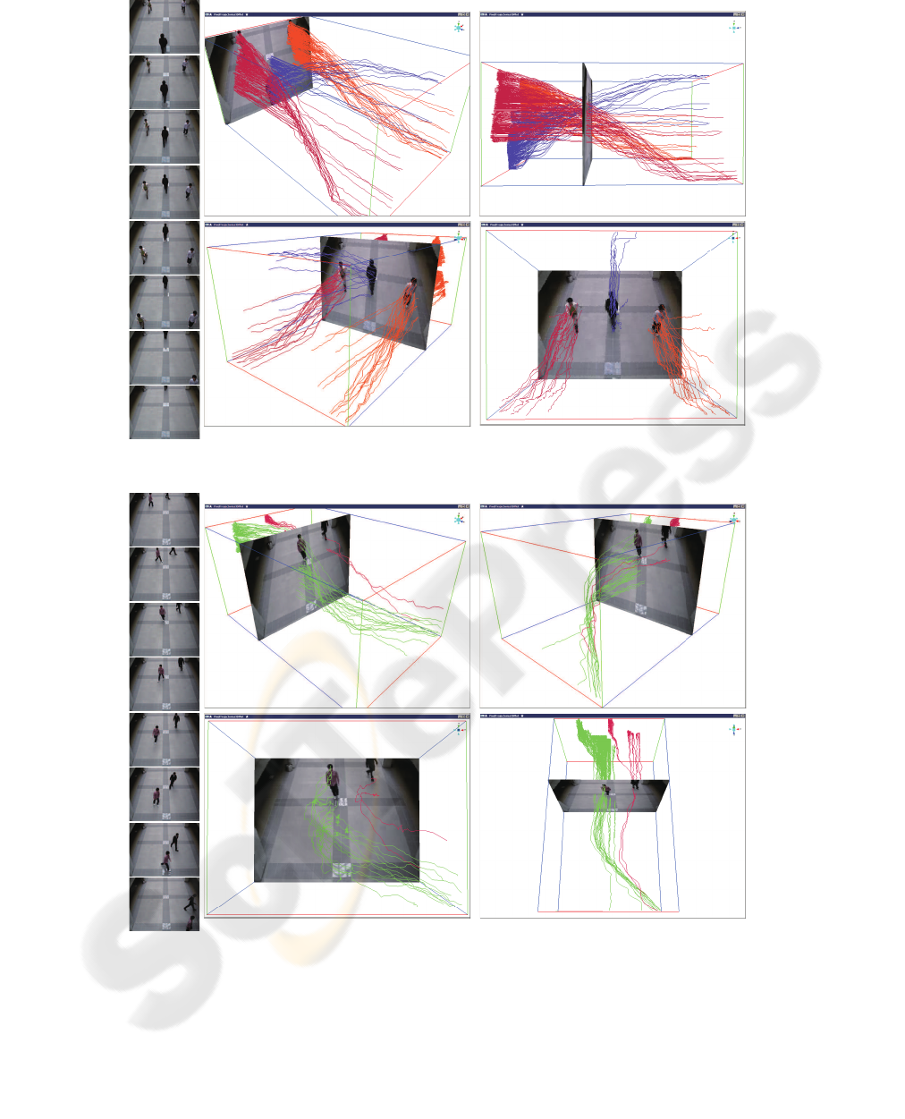
Figure 10: Result of Experiment 1. Three persons are well separated.
Figure 11: Result of Experiment 2. It can extract complex trajectories well.
• Three people walking in different directions.
Frame count is 107 and he image size is 200*150.
T is 50.
• Two people walks difference nonlinearly by each
direction . Frame number is 183. Image size is
200× 150. T is 30.
• Arms moving simultaneously. Frame count is 98,
image size is 200× 150. T is 40.
• Roller coaster with water splash. Frame count is
17. Image size is 288× 192. T is 20.
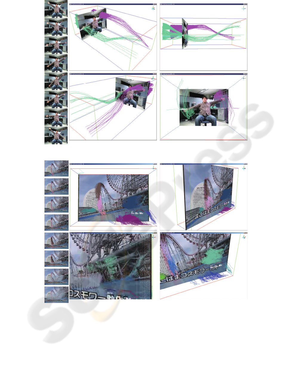
Figure 12: Result of Experiment 3. Two arms are separated.
Figure 13: Result of Experiment 4. Roller coaster, water splash and water surface are well separated.
4.2 Results
Below are illustrations of the conditioned trajecto-
ries for times t
0
to t
n
for each data set(Figure. 10–
13). Note that, the amplitude of the z-axis has been
changed for convenience. Each different color indi-
cates a different object corresponding to a cluster.
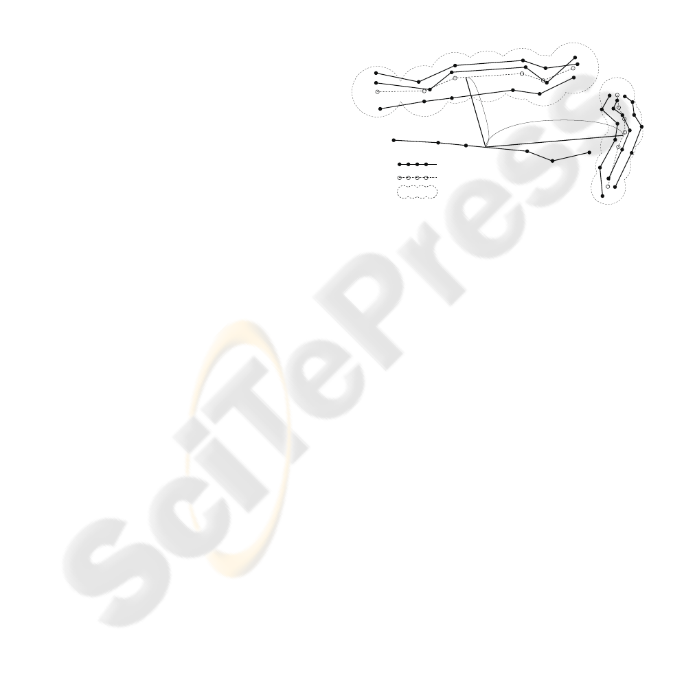
4.3 Comparison with KLT Tracker and
SIFT Tracker
Figure(14) shows the corresponding points and tra-
jectories in 3D space in which z-axis represents time.
The corresponding points, which are generated by
KLT and SIFT, appear discontinuously and the num-
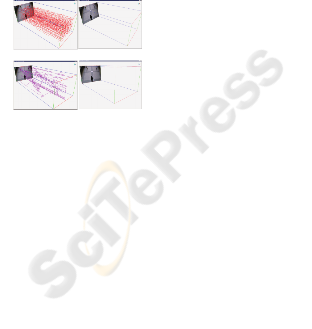
ber of them less than that of 2DCDP, for those rea-
sons, trajectories of those corresponding points can-
not be generated by adapting connecting system. In
this comparison, we used Stan Birchfield’s KLT(Stan,
2009) and Rob Hess’s SIFT(Hess, 2009) implementa-
tions.
Figure 14: Comparing with KLT Tracker and SIFT. Corre-
sponding points of KLT and SIFT are plotted to the left fig-
ure, and trajectories of those coresponding points are plot-
ted to the right figure by adapting connecting system.
4.4 Discussion
In these experiments, density trajectories of simple
or complex movements could be acquired even with
low-resolution time-sequential images. The proposed
method is effective even for different movements by
two or more objects. Moreover, even if the movement
changed during the sequence, trajectories could still
be extracted. Even when objects have varying texture
and edges such that features cannot be detected, the
proposed method can still acquire trajectories for cor-
responding points. We also showed that the proposed
method is more effective than methods based of fea-
ture points such as KLT or SIFT, because 2DCDP can
identify many more accurate corresponding points
than KLT Tracker or SIFT Flow(Figure14). Further-
more, our method also finds trajectories even for non-
linear, complex, and detailed movement such as wave
splashes and the surface of the water (Figure13).
5 CONCLUSIONS
We havecreated a novelframework for extracting mo-
tion features from time-sequential images in a few
steps. We also developed an optimal full-pixel match-
ing method called two-dimensional continuous dy-
namic programming (2DCDP) that achieved image
recognition that supports segmentation for free and
full pixel matching. We applied 2DCDP to object
tracking and utilized data for corresponding points
provided by 2DCDP as input for extracting pixel tra-
jectories and could compute density trajectories of
moving objects. We were able to extract trajectories
and segment objects from various type of motion with
low resolution over many frames. Finally, we vali-
dated advantages of the proposed method (2DCDP +
trajectory Clustering).
6 FUTURE WORK
The present approach has not considered occlusion
and decreasing trajectories. Therefore, when objects
appear in succession on the screen, the trajectory of
a rear object is integrated into that of a front object.
Because only a few pixels represent the object trajec-
tories are integrated over time, and so the number of
trajectories decreases. If the resolution of the time-
sequential images increases so that the number of pix-
els forming the target object is increased, many trajec-
tories can be calculated more accurately. Further, the
time space is divided and clusters can re-form in each
time space, and so the decrease in number of trajecto-
ries can be reduced if the clustering results are merged
through the time axis. It is also necessary to remove
outlier noise trajectories to improve the accuracy.
This method is applicable for background detec-
tion and subtraction from video captured by a moving
camera. By analysing a vector field and extracting the
majority 2DCDP vector, our method can divide back-
ground and foreground. It is able to apply a presump-
tion of camera motion. The majority vector field is the
background, which can be removed to target moving
objects. Our experiments indicate that we can also
consider applying the method to gesture recognition
and to novel human interface such as lip reading and
expression recognition.
ACKNOWLEDGEMENTS
I express my gratitude to members of the Image Pro-
cessing Laboratory for their cooperation in experi-
ments.

REFERENCES
Dan, M., Kazuhiro, O., and Junji, Y. (2009). Memory-
based particle filter for face pose tracking robust under
complex dynamics. Proc. of IEEE CVPR2009, 0:999–
1006.
Gonzalez, R. C. and Woods, R. E. (2001). Digital Im-
age Processing Second Edition. Prentice-Hall Inter-
national.
Hess, R. (2009). Sift feature detector. http://web.engr.orego
nstate.edu/∼hess/.
Lowe, D. G. (2004). Distinctive image features from scale-
invariant keypoints. Int. Journal of Computer Vision,
60(2):91–110.
Mochiki, R. and Katto, J. (2007). Human tracking by par-
ticle filter using haar-like feature. Proc. of the IEICE
General Conference, 2007(2):121.
Nakagawa, H., Habe, H., and Kidode, M. (2009). Efficient
prior acquisition of human existence by using past hu-
man trajectories and color of image. Technical report
of IEICE. PRMU, 108(484):305–312.
Oka, R. (1998). Spotting method for classification of real
world data. The Computer Journal, 41(8):559–565.
Shi, J. and Tomasi, C. (1994). Good features to track. In
Proc. of IEEE Conference on CVPR1994, pages 593 –
600.
Stan, B. (2009). KLT: an implementation of
the kanade lucas tomasi feature tracker.
http://www.ces.clemson.edu/∼stb/klt/index.html.
Sugimura, D., Kitani, K. M., Okabe, T., Sato, Y., and Sugi-
moto, A. (2009). Tracking people in crowds based on
clustering feature trajectories using gait features and
local appearances. In Proc. of MIRU2009, pages 135–
142.
Takayoshi, Y., Hironobu, F., Shihong, L., and Masato, K.
(2008). Human tracking based on soft decision feature
and online real boosting. In Proc. of MIRU2008, pages
12–19.
Takeuchi, D., Ito, Y., Yamashita, A., and Kaneko, T. (2009).
Multi-viewpoint person tracking based on face detec-
tion of arbitrary pose and mean-shift algorithm. ITE
Technical Report, 33(11):69–72.
Tsuduki, Y., Fujiyoshi, H., and Kanade, T. (2007). Mean
shift-based point feature tracking using sift. IPSJ SIG
Technical Reports, 49(6):101–108.
V. Rabaud, S. Belongie (2006). Counting Crowded Moving
Objects. In Proc. of IEEE CVPR 2006, volume Vol. 1,
pages 705–711.
VIOLA, P. (2001). Rapid object detection using a boosted
cascade of simple features. Proc. of IEEE CVPR2001,
pages 511–518.
Yaguchi, Y., Iseki, K., and Oka, R. (2009). Optimal Pixel
Matching between Images. In Proc. of PSIVT 2009,
pages 597–610.
Yilmaz, A., Javed, O., and Shah, M. (2006). Object track-
ing: A survey. ACM Computing Surveys (CSUR),
38(4).
Yuji, T. and Hironobu, F. (2009). A method for visualizing
pedestrian traffic flow using sift feature point tracking.
In Proc. of IEEE PSIVT2009.
