
CATADIOPTRIC MULTIVIEW POSE ESTIMATION
FOR ROBOTIC PICK AND PLACE
Markus Heber, Matthias R¨uther and Horst Bischof
Institute for Computer Graphics and Vision, Graz University of Technology, Inffeldgasse 16/II, Graz, Austria
Keywords:
Mirror symmetry, Object pose, Contour matching, Industrial application.
Abstract:
Robotic handling of objects requires exact knowledge of the object pose. In this work, we propose a novel
vision system, allowing robust and accurate pose estimation of objects, which are grasped and held in unknown
pose by an industrial manipulator. For superior robustness, we solely rely on object contour as a visual cue.
We address the apparent problems of object symmetry and ambiguous perspective by acquiring multiple views
of the object cheaply and accurately, through a mirror system. Self-calibration of the mirror setup allows us to
model the mirror geometry and perform metric multiview contour matching with a known 3D model.
1 INTRODUCTION
Automated robotic handling processes rely on exact
knowledge of type and pose of the object to manipu-
late. So the problem of pose estimation is concerned
with determining object position and orientation rela-
tive to a reference coordinate frame. We especially
address the case of uniformly textured, opaque or
specularly reflecting objects. Approaches based on
3D reconstruction will fail due to robustness prob-
lems. Here, the only robust geometric cue is the ob-
ject contour, which can be segmented even on trans-
parent objects with specialized illumination. If the 3D
model is known a priori, contour shape matching and
registration techniques are the method of choice, to
avoid laborious appearance teaching.
An early pose estimation approach was introduced by
Phong et al. (Phong et al., 1995). It is based on line
and point correspondences between images of an ob-
ject of different pose. The six extrinsic parameters,
represented by dual quaternions, are estimated by
minimizing a quadric error function. Their minimiza-
tion technique is compared with the Newton method,
and Levenberg-Marquardtoptimization. Pose estima-
tion results are compared to ground truth data, as well
as the results of Faugeras and Toscani (Faugeras and
Toscani, 1986).
Byne and Anderson (Byne and Anderson, 1998) in-
troduced a CAD-based method. They combine geo-
metric descriptions of a 3D model, appearance infor-
mation and functional information. Online, they gen-
erate hypotheses from these models, based on either
edge information, or classification of surface material
type. Final pose refinement is done by maximizing a
fitting score.
An extensive review of pose estimation methods is
given by Rosenhahn et al. (Rosenhahn et al., 2004).
In (Rosenhahn and Sommer, 2004) Rosenhahn and
Sommer introduced a free-form surface based ap-
proach, where surface models are represented by
three Fourier descriptors. They estimate the corre-
sponding 3D silhouettes and refine the pose using the
iterative closest point algorithm (ICP), introduced by
Zhang (Zhang, 1994). In a subsequent work, Rosen-
hahn et al. (Rosenhahn et al., 2006) compared ICP
and a variational method for shape registration via
level sets. Evaluation results suggest, that the vari-
ational method is more robust against large pose vari-
ations, while ICP is more accurate.
A recent approach to CAD-based pose estimation is
introduced by Ulrich et al. (Ulrich et al., 2009), where
hierarchical views of a CAD model are generated at
multiple scale levels. For shape matching they evalu-
ate a similarity measure based on gradient orientation
differences. Their experiments show considerable ro-
bustness to occlusions, clutter and contrast changes.
Chang et al. (Chang et al., 2009) investigated pose es-
timation and segmentation of specular objects. Spec-
ular reflections and specular flow of a known 3D
model are used for localization and pose estimation.
Experiments show the feasibility of their method un-
der sparse highlights and small environmental mo-
423
Heber M., Rüther M. and Bischof H. (2010).
CATADIOPTRIC MULTIVIEW POSE ESTIMATION FOR ROBOTIC PICK AND PLACE.
In Proceedings of the International Conference on Computer Vision Theory and Applications, pages 423-426
DOI: 10.5220/0002822704230426
Copyright
c
SciTePress

tion.
Most approaches assume the presence of edges or any
kind of local features. Furthermore, object symme-
tries and shape ambiguities are not considered. Our
method in contrast also works with untextured, trans-
parent and shiny objects. They can also have smooth
surface geometry which is not easily approximated by
polyhedral models. In our work, we rely only on ob-
ject contour information. To overcome the problem
of contour symmetry and ambiguous views, we pro-
pose a multi-mirror system in combination with a sin-
gle camera and light source. The result is a cheap,
perfectly synchronized multiview system, which can
be self-calibrated from any known reference object.
Furthermore, our pose estimation procedure is insen-
sitive to local minima, because an exhaustive search
over the space of object contours is performed.
2 CATADIOPTRIC GEOMETRY
A central perspective camera projection matrix is
given by a 3 × 4 matrix P, computed from camera
calibration matrix K, which includes the five intrin-
sic camera parameters, rotation R and translation t:
P = K[R|t] (1)
A 3D plane is defined as:
n
T
x+ d = 0, (2)
with normal vector n and the distance to the ori-
gin d. Reflections in 3D space are Euclidean trans-
formations, which additionally perform orientation
changes. Algebraically, a reflection is given by a ma-
trix D
4×4
, which is able to reflect points x, planes Π
and cameras P over a reflection plane:
x
′
= D
T
x, Π
′
= D
−1
Π, P
′
= PD
T
. (3)
Catadioptric devices use reflective devices in a cam-
era’s field of view to capture an object from more than
one viewpoint. Additionally, catadioptric stereo has
geometric and radiometric advantages. One geomet-
ric advantage is the reduced number of camera param-
eters. One radiometric advantage is the replication of
light sources due to mirror reflections. The relation
between the real camera and its virtual reflection is
defined by the mirror reflection matrix D, which is
defined by the mirror normal n, the camera-mirror-
distance d and the camera coordinate frame origin
e
c (Gluckman and Nayar, 2001):
D =
I− 2nn
T
e
c− 2dn
0 1
=
R t
0 1
. (4)
A virtual camera is computed from P
real
as
P
virtual
= P
real
D
T
. (5)
3 POSE ESTIMATION
Pose estimation is based on matching measured con-
tours from all mirror views against a set of pre-
generated synthetic contours. Using a known 3D
model, and camera-mirror geometry as obtained from
calibration, the object is rendered in different poses.
From each rendered image, contours are extracted
and added to a database. The set of all rendered im-
ages covers the space of possible object orientations
in front of the camera, sampled in discrete intervals.
Pose estimation subsequently is reduced to an exhaus-
tive search within this database. The classification re-
sult is guaranteed to be globally optimal with respect
to the discretized space of orientations.
3.1 System Calibration
We assume the camera projection center to be lo-
cated at the world coordinate origin. Hence, camera
rotation R is the identity matrix and translation t is
zero. Intrinsic calibration is performed as proposed
by Zhang (Zhang, 1999). The mirror calibration pro-
cedure used within our approach is based on the work
of Hu et al. (Hu et al., 2005), where first the mir-
ror plane normal n is estimated, followed by camera-
mirror-distance d. For computation of n, two pairs
of corresponding points between real view and each
mirror view are required. These correspondences are
obtained via the object convexhull in the real and mir-
ror views. There are exactly two lines, which are tan-
gent to both convex hulls. They are called limitation
lines and provide a pair of corresponding points each.
Furthermore, their intersection provides the vanish-
ing point vp of n, which coincidentally describes the
epipole e of the virtual camera. Mirror normal n is
computed by evaluating the direction of the viewing
ray through e in the image:
n = (n
x
,n
y
,n
z
)
T
= K
−1
e. (6)
Camera-mirror-distance d is computed with knowl-
edge of a single object point (x,y) and its mirrored
correspondence (x
′
,y
′
):
d =
∆uz
0
2(u
′
n
z
− n
x
)
, (7)
where (u,v) are normalized image coordinates, and
∆u = u
′
− u. The nominal distance between camera
center and 3D world point z
0
is set to 1, which results
in a system calibration up to an unknown scaling fac-
tor (Hu et al., 2005). In the case of multiple mirrors,
these correspondencescannot be uniquely determined
over all views. Hence, an additional point correspon-
dence is established by evaluating the centroid of a
VISAPP 2010 - International Conference on Computer Vision Theory and Applications
424
sphere. With known sphere radius, the calibration can
be upgraded to metric, including exact scale.
3.2 Contour Representation and
Similarity Metric
The matching process itself needs to be fast and accu-
rate, but it does not have to be scale- or rotation invari-
ant. We therefore choose a simple approach, where
each contour is represented by a set S
i
of neighboring
contour points S
i
= {x
i1
...x
in
}. Without scale invari-
ance, identical contours have approximately the same
number of points, and a similarity metric is computed,
using the sum of squared distances of corresponding
points:
e
ij
=
n
∑
k=1
|x
ik
− x
jk
|
2
, (8)
where e
ij
is the similarity error between two contours
S
i
and S
j
.
3.3 Contour Extraction and Matching
Shape matching is an exhaustive search for the
best matching synthetic contour in all views. The
camera intrinsics, mirror parameters, and a contour
database, which stores the synthetic object con-
tours for all orientations, are given. Experiments
on synthetic contour matching as well as real ob-
ject pose estimation (see Section 4) have shown
that it is sufficient to consider a discrete set of
orientations. Considering the space of all object
orientations as the set of all roll, pitch and yaw-angles
(r,p,y)
T
,r ∈ [0
◦
,360
◦
],p ∈ [0
◦
,360
◦
],y ∈ [0
◦
,360
◦
],
we discretize in 12
◦
steps and have 27k database
entries. Selection of the discretization step depends
on the underlying application as well as available
hardware. Modern graphics cards allow rendering of
six views of a detailed 3D model at over 100fps, and
a database of 27k entries is generated in roughly five
minutes. To estimate an object pose, the contours are
extracted from an image and compared to entries in
the database, according to the metric in Section 3.2.
To further speed up the matching process, contour
features like length and aspect ratio are used to reject
dissimilar contours early on.
4 EXPERIMENTS
We focus on object symmetries and ambiguities, be-
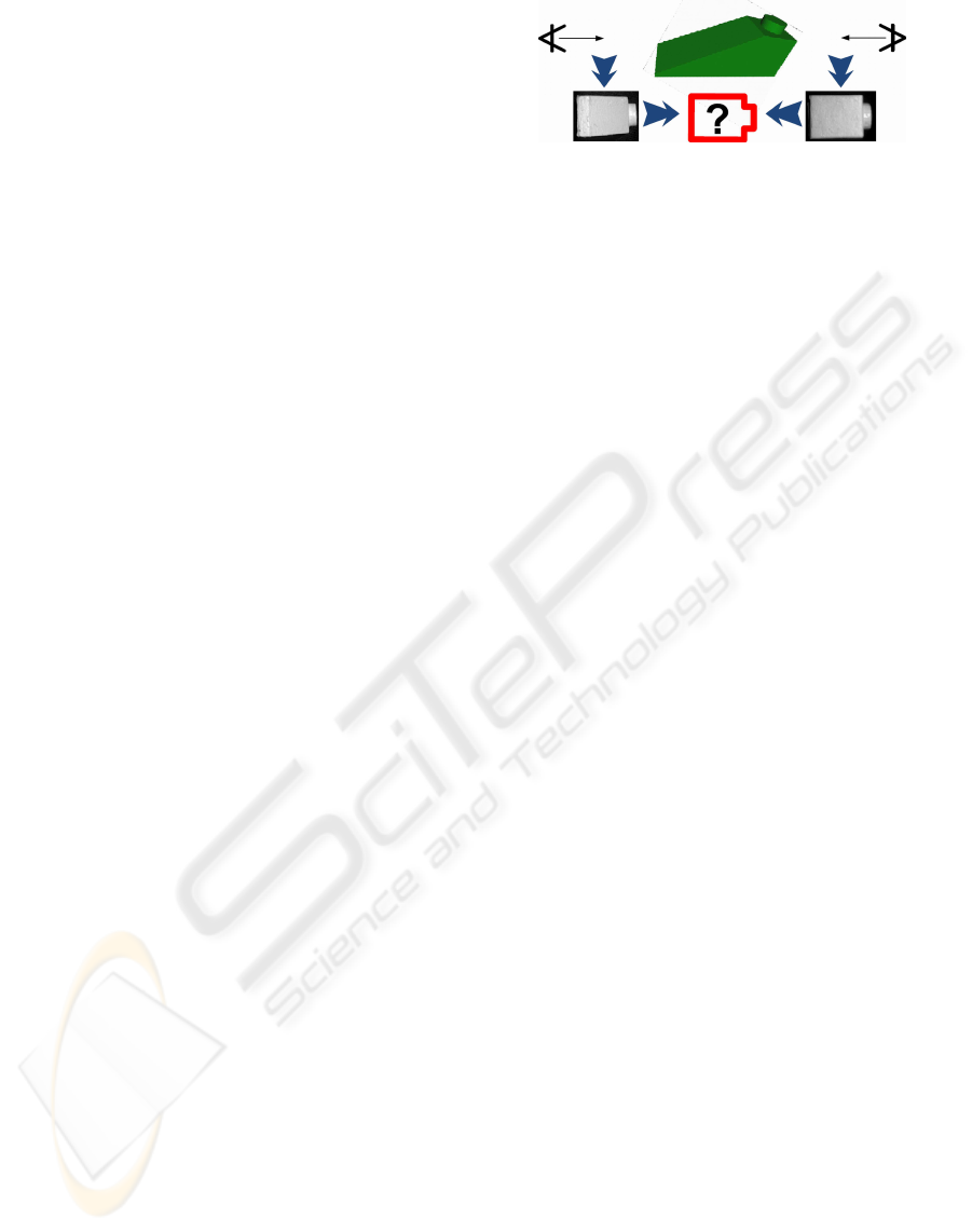
cause these are the most challenging cases. In Fig-
ure 1 a typical symmetry case is shown. Our ex-
perimental hardware setup consists of a monochrome
Figure 1: Tow views of a sample test object. Extracted im-
age object contours are similar due to object symmetry.
CCD camera, and five planar mirrors. The mirrors
are placed transversely in front of the camera. A LED
light source illuminates the object coaxially against
defined background to simplify the contour extrac-
tion process. Due to the transversal placement of
the mirrors, light sources are replicated, which results
in approximately diffuse illumination conditions and
avoids shading on round object borders.
An object is placed in unknown orientation inside
the catadioptric setup. We evaluated our setup with
three different test objects: (a) 5× 10× 5mm block,
providing a front-back symmetry, if only image con-
tours are taken into account, (b) 5× 15× 5mm slant-
ing block, providing an upside-down symmetry, and
(c) 10× 10× 5mm slanting block, also providing an
upside-down symmetry.
4.1 Self Calibration
The system is calibrated as described in Section 3.1.
We evaluated the reprojection error (RE) and used it
as a measure of calibration accuracy. Over severalcal-
ibration runs we achieved an average RE of 0.01px.
This comes up to a geometric error of 2µm at a cam-
era object distance of 350mm.
4.2 Pose Estimation
Pose estimation has been evaluated on synthetic con-
tours as well as real objects, with a focus on sym-
metries, that cannot be resolved from a single view.
These include upside-down flips (uds) and front-back
flips (fbs). Additionally, different rotations (rot) have
been evaluated. The upside-down ambiguity can be
resolved with our proposed method. For symmet-
ric blocks like object (a), a front-back symmetry re-
mains, and quadric blocks would lead to four equiv-
alent poses. In order to evaluate correctness, pose
estimation has also been evaluated on synthetic data.
Synthetic contours with slightly different poses to the
contour database poses were generated. According to
a discretization step of 12
◦
, the residual error should
not be greater than 6
◦
for a correct match. As pre-
sented in Table 1, our results lie within this expected
range. Numerical results on the real test objects are
CATADIOPTRIC MULTIVIEW POSE ESTIMATION FOR ROBOTIC PICK AND PLACE
425
given in Table 2. For each object, (uds), (fbs) as well
as different rotations (rot) have been evaluated. For
object (a), ’?’ means a successful match, but a front-
back symmetry could not be resolved. Figure 2 shows
exemplary matching results.
Table 1: Results on pose estimation of randomly generated
synthetic contours at a discretization step of 12
◦
.
Object Runs Avg. rpy Errors
(a) 10 r = 5.2
◦
,p = 3.4
◦
,y = 3.5
◦
(b) 10 r = 6.0
◦
,p = 3.2
◦
,y = 5.4
◦
(c) 13 r = 4.7
◦
,p = 4.6
◦
,y = 4.5
◦
Table 2: Results on pose estimation of real test objects,
where e.g 1/2 denotes that one out of two runs was correct.
Object uds fbs rot
(a) 5/ 5 ’?’ / 3 4 / 4
(b) 4/ 5 2/ 3 3/ 5
(c) 5/ 4 3/ 2 5/ 3
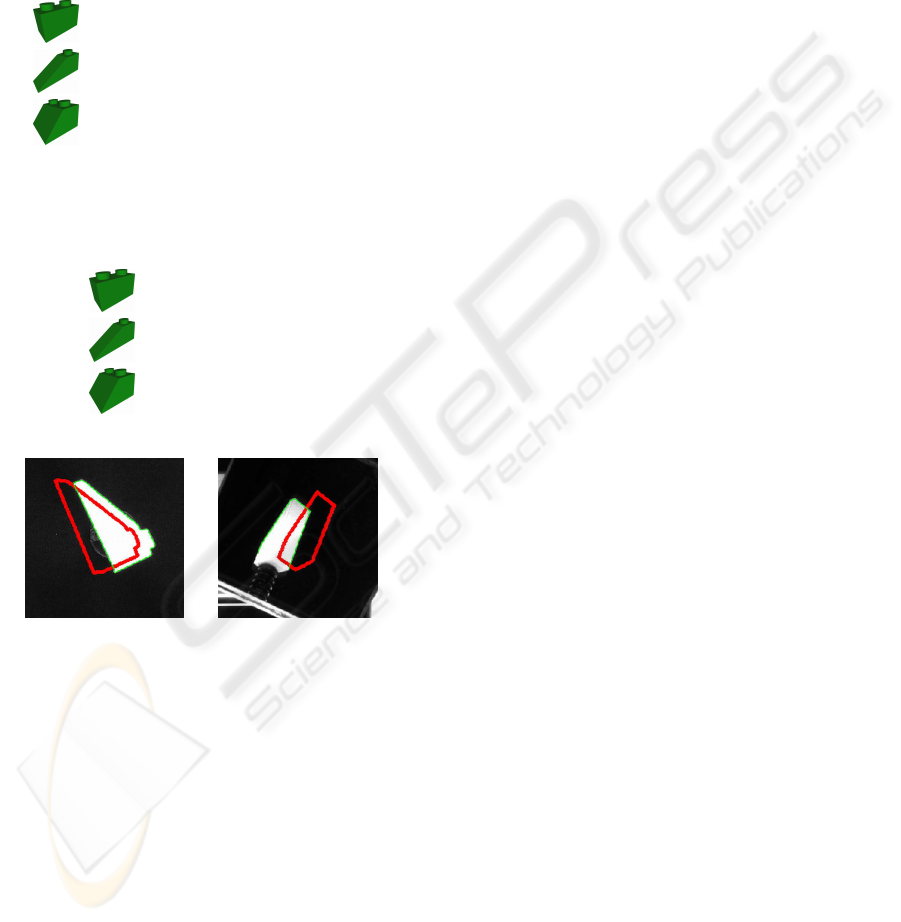
(a) (b)
Figure 2: Two examples of contour matching results. Match
result are shown with a translational offset for better visual-
ization.
5 CONCLUSIONS
We have presented a novel method for object pose es-
timation. Our approach benefits from employing mir-
rors in the optical path, due to replicated object illu-
mination, and multiple perfectly synchronized views.
We have shown that object symmetry and ambiguous
perspective are better resolved than using a monocu-
lar setup. The problem of object pose estimation was
reduced to an exhaustive search of matching contours.
Experimental results show that this procedure does
not get stuck in local minima. Most object symme-
tries were resolved. Creation and storage of a contour
database is feasible up to a certain discretization step.
Our choice of 12
◦
might not be sufficient to resolve
fine details of some objects, though. Future work in-
cludes the intelligent organization of a more dense
database by clustering of similar views. Furthermore,
evaluation of real objects with given ground truth on
their pose will be an issue. Further iterative 3D ob-
ject registration can also be taken into account. To
overcome the discretization error, one could consider
further pose refinement, using iterative methods like
ICP.
REFERENCES
Byne, J. and Anderson, J. (1998). A CAD based computer
vision system. IVC, 16(8).
Chang, J. Y., Rsakar, R., and Agrawal, A. (2009). 3D pose
estimation and segmentation using specular cues. In
Proc. CVPR 2009, Miami, FL.
Faugeras, O. D. and Toscani, G. (1986). The calibration
problem for stereo. In Proc. CVPR, Miami Beach.
Gluckman, J. and Nayar, S. K. (2001). Catadioptric stereo
using planar mirrors. Int. J. Comput. Vision, 44(1).
Hu, B., Brown, C., and Nelson, R. (2005). Multiple-view
3-D reconstruction using a mirror. Technical report,
University of Rochester.
Phong, T. Q., Horaud, R., Yassine, A., and Tao, P. D. (1995).
Object pose from 2-D to 3-D point and line correspon-
dences. Int. J. Comput. Vision, 15(3).
Rosenhahn, B., Brox, T., Cremers, D., and Seidel, H.-P.
(2006). A comparison of shape matching methods for
contour based pose estimation. Combinatorial Image
Analysis.
Rosenhahn, B., Perwass, C., and Sommer, G. (2004).
CVOnline: Foundations about 2D-3D pose estima-
tion. CVOnline.
Rosenhahn, B. and Sommer, G. (2004). Pose estimation
of free-form objects. In Proc. ECCV 2004, Part I, T.
Pajdla and J. Matas (Eds.).
Ulrich, M., Wiedemann, C., and Steger, C. (2009). CAD-
based recognition of 3D objects in monocular images.
In Proc. ICRA 2009, Kobe, Japan.
Zhang, Z. (1994). Iterative point matching for registration
of free-form curves and surfaces. Int. J. Comput. Vi-
sion, 13(2).
Zhang, Z. (1999). Flexible camera calibration by viewing a
plane from unknown orientations. In Proc. ICCV.
VISAPP 2010 - International Conference on Computer Vision Theory and Applications
426
