
A Metamodelling Approach to the Management of
Intermodal Transportation Networks
Valentina Boschian
1
, Mariagrazia Dotoli
2
, Maria Pia Fanti
2
Giorgio Iacobellis
2
and Walter Ukovich
1
1
Department of Electronics, Electrical, Engineering and Computer Science
University of Trieste, Trieste, Italy
2
Department of Electrical and Electronic Engineering 70125 Bari, Italy
Abstract. The paper develops a novel and broad metamodel of a generic Inter-
modal Transportation Network (ITN), devoted to provide a reference model for
the real time management and control of such systems. In order to take opera-
tional decisions, the presented model describes in detail the ITN structure and
dynamic evolution that is updated on the basis of the information obtained in
real time by modern information and communication technologies tools. The
proposed metamodelling approach consists in employing a top down procedure
and is based on the UML formalism, a graphic and textual modelling language
intended to describe systems from structural and dynamics viewpoints. Hence,
the paper models a generic ITN starting from the network description and
shows as an example the metamodel of one of the most important nodes that
compose it: the port subsystem. To this aim, we present the main UML dia-
grams describing the structure and dynamics of a case study.
1 Introduction
An Intermodal Transportation Network (ITN) can be defined as a logistically linked
system integrating different transportation modes (rail, ocean vessel, truck etc.) to
move freight or people from origin to destination in a timely manner [9]. The 21st
century will see a renewed focus on ITN, driven by the necessity of moving ever
growing quantities of goods and by the technological evolution each of the transpor-
tation modes has recently gone through. However, ITN decision making is a very
complex process, due to the dynamical and large scale nature of the ITN, the hierar-
chical structure of decisions, as well as the randomness of various inputs and opera-
tions. Typically, ITN management techniques are based on a three-level hierarchy:
strategic, tactical and operational ones. Strategic planning involves ITN design and
considers time horizons of a few years. Tactical planning basically refers to the opti-
mization of the flow of goods and services through a given ITN. Finally, operational
planning is short-range planning and involves transportation scheduling at all trans-
porters on an hour-to-hour basis, subject to the changing market conditions as well as
to unforeseen transportation requests and accidents.
Boschian V., Dotoli M., Fanti M., Iacobellis G. and Ukovich W. (2009).
A Metamodelling Approach to the Management of Intermodal Transportation Networks.
In Proceedings of the 3rd International Workshop on Intelligent Vehicle Controls & Intelligent Transportation Systems, pages 96-105
Copyright
c
SciTePress

The related literature has largely addressed the ITN modelling and management prob-
lems at strategic and tactical levels. Recently, entrepreneurs and researchers are being
attracted by the key problem of using effectively and efficiently the latest develop-
ments of ICT (Information and Communication Technologies) for ITN operational
management [6], [11], [12], [13]. In fact, since intermodal transportation is more
data-intensive than conventional transportation, ICT are considered a primary “ena-
bling tool” for the safe and efficient real time management and operation of ITN.
Indeed, today the effective use of the modern ICT tools has made it possible to know
the state of the system in real time and therefore manage and change on-line paths,
vehicle flows, deliveries and orders. In order to operate such choices, there is a need
of dynamic models that can track the state changes of the various system components
and determine operation indices typical of the real time management, such as utiliza-
tion, traffic indices and delivery delays [14]. In the domain of ITN models at the
operational level we recall the class of discrete event system models [1], [3], [4] and
of the simulation models [13], [14]. However, the above models are designed to de-
scribe a particular ITN and do not fully take into account the multiplicity of elements
that can influence the ITN dynamics and the corresponding information structure.
Since ITN are often complex and distributed systems, they have also been effectively
represented by multi-agent techniques. However, this promising approach to transpor-
tation and traffic management is still at its early stages [2].
This paper develops a novel metamodel of ITN at the operational level intended
for real time management and control of such systems. The metamodel has a general
and modular structure and is characterized by high information integration. In order
to take operational decisions, the presented model describes in adequate detail the
structure and dynamic evolution of the ITN and is updated on the basis of data ex-
changed by the players in the system and information obtained in real time by using
modern ICT tools [7]. The proposed approach consists in applying metamodelling by
a top down procedure based on the UML formalism [9], [10], a graphic and textual
modelling language intended to understand and describe systems from various view-
points. Hence, UML enables us to describe the structure and dynamics of a generic
ITN starting from the description of the network, until the model of the most impor-
tant entities that compose it (classes) and their corresponding activities. Moreover,
UML unifies the formalism by using appropriate and effective diagrams that can be
easily translated into a simulation software. Indeed, the approach to the management
and control of ITN is based on the construction of a reference model that simulates
the evolution and dynamics of ITN and provides to the control modules the knowl-
edge base necessary for decisions in real time. To this aim, the model reproduces the
behaviour of the ITN by storing the real events such as variations in demand and
orders, blockages, accidents, breaks and all those occurrences that interact with the
flow and management of materials and transporters. Hence, based on the knowledge
of the reference model state and the events, decision makers can make the appropriate
choices optimizing suitable performance indices. To the best of the authors’ knowl-
edge, such a UML based metamodel approach has never before been proposed for
ITN.
The paper is organized as follows. Section 2 describes the main steps of the ITN
metamodel approach. Subsequently, sections 3 and 4 respectively describe the static
and dynamic diagrams in the ITN metamodel. A conclusion section closes the paper.
97

2 The Metamodel of Intermodal Transportation Networks
We consider a generic ITN constituted by a set of terminals (ports, airports, railway
stations, etc.), together with the interconnections between them and land infrastruc-
tures. Metamodelling is a technique that applies to models [5]. A metamodel provides
an accurate description of the constructs and rules needed to obtain semantic models
and encapsulates all the concepts that are necessary to describe the structure and dy-
namics of a particular system.
The metamodelling approach presented in this paper is a top-down approach that
decomposes the system to gain insight into its compositional sub-systems. In the top-
down approach an overview of the ITN is formulated, specifying any first-level sub-
systems: ports, airports, railway stations, intermodal terminals, ground, sea and air
connections, information systems, carrier and freight forwarder. Subsequently, each
subsystem is refined in detail from the structural and dynamical points of view, using
suitable UML diagrams, such as class diagrams and activity diagrams. In the follow-
ing sections we detail the main steps of the proposed ITN metamodelling approach.
First, a procedure addressing static models is devised, defining the so-called package
diagram and the class diagrams. Subsequently, process flows are considered and
dynamic models are obtained, by referring to the so-called activity diagrams.
3 Static Modelling of Intermodal Transportation Networks
3.1 The Package Diagram
The first step of the presented metamodelling approach consists in identifying the
main subsystems composing an ITN. These can be divided into structural subsystems
(i.e., ports, airports, railway stations, intermodal terminals, ground, sea and air con-
nections, carrier and freight forwarder) and the information system. They represent
the generic concepts used within the metamodelling framework and are modelled in
UML by packages. However, such subsystems are complex nodes that can be consid-
ered composed by other generic objects (or classes). Hence, we represent the overall
ITN by the UML package diagram [9], [10]. Packages are groups of entities related to
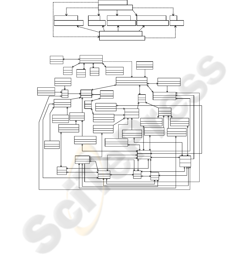
each other. Figure 1 depicts the package diagram of a generic ITN. We identify the
following seven packages that form the ITN: the port, the airport, the railway station,
the ground, sea and air connection, the intermodal terminal, the information system
and the carrier and freight forwarder (see Fig. 1). Each package is composed by dif-
ferent classes representing structural basic objects interconnected with each other.
Arrows show the cases in which a class in one package needs to use a class in another
package. This causes a dependency between packages: for example, the information
system is updated on the basis of data obtained in real time using modern ICT tools.
We assume that each package includes an information class representing the informa-
tive structure devoted to manage the considered system. However, we consider also
the possibility of the existence of a centralized information system that can manage
and coordinate different packages. For example, the port package contains an infor-
mation class that manages the flow of trucks, trains, cranes, etc. On the other hand,
98
the external and higher level information system can control the interactions between
the port and the infrastructures, by receiving data from the port area and the ground,
sea, rail and air connections.
PortIntermodal terminalGround Sea AirRailway Station Airport
Information System
Carrier and freight forwarder
Fig. 1. The package diagram of the ITN: arrows show dependence among packages.
Port_AreaQuay
Loading_Area
Unloading_Area
Parking_Area
Truck_Parking_Area
Tow_Parking_Area
Container_Yard
Landside_Yard
Seaside_Yard
Crane_Area
Crane
Queue
Gate_Queue
Exit_Queue
Truck_Gate_Queue
Ship_Gate_Queue
Crane_Gate_Queue
Parking_Gate_Queue
Train_Gate_Queue
Parking_Exit_Queue
Truck_Exit_Queue
Ship_Exit_Queue
Train_Exit_Queue
Transportation_Means
Train
Truck
Ship
Tow
Customs_Authority
check
Intermodal_Transport_System
Container Pallet
Freight
Costs Manager
Management_system
Routing
Sequencing
Priority
Synchronization
Timing
Fig. 2. The port class diagram: connections show relationships among objects in the class.
3.2 The Class Diagrams
The subsequent step of the static modelling consists in setting up the so-called class
diagrams, specifying the configuration of the various packages defined in the previ-
ously discussed package diagram [9], [10]. A class diagram describes the types of
objects in the ITN and the various static relationships between them. These are repre-
sented by different pictorial connections and may be relationships of association
99

(solid line), aggregation (solid line with a clear diamond at one end), composition
(solid line with a filled diamond at one end), inheritance or generalization (solid line
with a clear triangle at one end), realization (dashed line with a clear triangle at one
end) and dependency (dashed line with an arrow at one end). Moreover, the class
diagram may show the features of a class, i.e. the name, attributes and operations of
the class.
As an example, we show in Fig. 2 the class diagram of one of the packages in Fig.
1, namely the Port: for the sake of brevity we omit the class diagrams of the remain-
ing packages in Fig.1, since they may be set-up similarly to the diagram described
here. The main classes included in the diagram in Fig. 2 are the Intermo-
dal_Transport_System, the Management_System and the Cost_Manager. In the se-
quel we briefly describe such classes together with their typical attributes and meth-
ods. Obviously, these features may vary depending on the ITN under study [14].
The Intermodal_Transport_System class represents the overall port terminal sys-
tem. The class attributes are: 1) the dynamic lists of ships, trains and trucks currently
in the terminal; 2) the dynamic lists of ships, trains and trucks already served by the
operators in the terminal or by the quay cranes, waiting for permission to exit from
the terminal; 3) the dynamic lists of ships, trains and trucks queued and waiting for
service; 4) the dynamic lists of ships, trains and trucks currently being served; 5) the
dynamic lists of ships, trains and trucks currently leaving the terminal; 6) the lists of
occupied quay cranes and available ones. The class methods are: 1) the registration of
ships, trains and trucks entering the terminal; 2) the extraction from the list of ships,
trains and trucks waiting for service; 3) the extraction from the list of available
cranes; 4) the assignment of a crane to a specific task of freight loading/unloading; 5)
the crane activation; 6) the extraction from the list of ships, trains and trucks exiting
from the terminal; 7) the update of the list of served ships, trains and trucks; 8) the
update of the list of waiting ships, trains and trucks; 9) the update of the list of ships,
trains and trucks exiting the terminal; 10) the update of the list of available cranes.
The Intermodal_Transport_System class aggregates the following classes: Port_Area,
Queue, Transportation_Means and Customs_Authority.
The Port_Area class represents the physical port area, modelled generalizing the
following classes: Quay, where the ship loading/unloading processes take place, Con-
tainer_Yard, representing the freight stock area, Crane_Area, describing the crane
pick up and delivery point and Parking_Area, representing the zones where vehicles
are parked. Hence, all these classes inherit the properties and basic services of their
parent class, i.e. the Port_Area. This has the following attributes: 1) dimensions; 2)
list of occupied locations; 3) list of unoccupied locations; 4) opening time; 5) closing
time; 6) number of operators. Its methods are: 1) the extraction from a list of locations
in the port area; 2) the access control; 3) the assignment of a location to an entity
(ship, train, truck); 4) the clearing of a location upon the leaving of an entity. The
Container_Yard class defines the storage area where freight is stored and waits for
being delivered to their destination. The Quay class models the quay where ships are
loaded/unloaded. Hence, the Quay class aggregates the Ship class, while it general-
izes the Loading_Area and Unloading_Area classes. The Crane class attributes are: 1)
the crane type (quay crane loading/unloading freight onto/from the ship, stacker crane
retrieving/storing freight from the Container_Yard, automated guided vehicle or trac-
tor moving freight from the quay area to the container yard area, etc.); 2) the crane
100

identification number. The Loading_Area class models the ship loading area, while,
the Unloading_Area class represents the ships unloading area. The Parking_Area
class is the area where trucks wait either to be loaded or to be embarked. The class
also includes means of transportation waiting for any reason. The Parking_Area class
obviously includes the Truck class and generalizes the Truck_Parking_Area and
Tow_Parking_Area classes. The Container_Yard class includes the Container class
and generalizes the Seaside_Yard and Landside_Yard classes. The Seaside_Yard
(Landside_Yard) class represents the warehouse area where containers, freight, tow
or pallets to load on trains or trucks destined to the inland (to be shipped) are stored.
The Queue class enables the management of queues and the computation of wait-
ing times and hence of costs. The attributes of this class are: 1) the maximum number
of entities a queue may have; 2) the queue management policy; 3) the velocity of
queue management; 4) the costs associated to the waiting time in queue of a user; 5)
the queue identification number; 6) the current number of users in a queue; 7) a Boo-
lean flag indicating whether the queue is full. Its methods are: 1) the inclusion of an
entity in the queue; 2) the cancellation of an entity from the queue; 3) the queue man-
agement; 4) the queue cost computation. Its children classes are called Gate_Queue
and Exit_Queue, respectively representing the input and output queues in all the port,
e.g. queues in parking area, in crane area, etc. The Gate_Queue and Exit_Queue both
have as children classes those representing the truck, train, ship, parking and crane
queues. For instance, the Parking_Gate_Queue and the Parking_Exit_Queue classes
respectively represent the input and output truck queues in the parking area.
The Transportation_Means class represents the transportation means circulating in
the port, i.e., trucks, trains and ships. Hence it generalizes the Truck, Train and Ship
classes and is associated to the Customs_Authority class. Indeed, customs have the
task of controlling the arriving transportation means and applying the corresponding
taxes. The Transportation_Means class exhibits the attributes: 1) the transportation
means identification number; 2) the transportation means dimensions; 3) the carrier
name; 4) the category of transported goods (e.g., hazmat); 5) the goods place of ori-
gin; 6) the goods destination; 7) the goods weight; 8) the identification number of the
carried tows, containers, freight or pallet; 9) a Boolean flag indicating full load; 10)
the current waiting time for the unload and load operation. The class methods are as
follows: 1) the load/unload operation; 2) the waiting time computation. Note that the
class diagram shows that the Truck class is included in the Train and Ship classes,
while it aggregates the Tow, Container, Freight and Pallet classes. The Container
class includes the Freight and Pallet classes, which in turn includes the Freight class.
Note that both the Tow and Container class have one attribute, the identification
number. On the contrary, the Pallet class attributes are the identification number and
its capacity, while the Freight class attributes are the identification number and di-
mension. The Train class represents trains moving freight entering or exiting from the
port. Such a class includes the Container class and makes use of the Intermo-
dal_Transport_System class, so that trains remain in the railway as minimum time as
possible. The Ship class models ships berthed at the port. This class includes the
Container and Truck classes.
The Customs_Authority class represents the customs and their tasks of controlling
all transportation means and their freight and applying taxes. It is therefore connected
to the Transportation_Means class by an association function named “check”. Its
101

attributes are: 1) the opening and closing times; 2) the control time of goods; 3) the
number of customs operators. Its methods are: 1) the freight control; 2) the tax as-
signment.
The Management_System class is devoted to managing the whole Intermo-
dal_Transport_System class. This class provides the rules to perform choices and
decisions in the ITN. Hence, it uses the database provided by the Intermo-
dal_Transport_System class to elaborate the decisions. It aggregates the following
classes: the Synchronization class, introduced to minimize operation delays in the
intermodal terminal so as to maximize synchronization of operations; the Priority
class, which deals with the assignment of priorities to the transportation means (e.g.,
trucks transporting hazmat are assigned priority or a FIFO logic may be considered);
the Routing class, which describes the operation path that has to be followed; the
Sequencing class, assigning the subsequent operation that the system has to execute;
the Timing class, which determines the timing of the next operation.
Finally, the diagram in Fig. 2 includes the Costs_Manager class that computes the
managing costs of the container terminal. Hence, this class uses data stored in the
Intermodal_Transport_System and exhibits the cost calculation operations.
4 Dynamic Modelling of Intermodal Transportation Networks
In this section we employ activity diagrams to provide a “dynamic view” of the sys-
tem. Activity diagrams aim to describe the logic of the involved processes and the
workflow [9], [10]. They are similar to flowcharts, but they allow representations of
parallel elaborations in order to explain the critical points in the processes and work-
flow of the whole system by pointing out all the possible paths, parallel activities and
their subdivisions. The main elements of these diagrams are: the initial activity (de-
noted by a solid circle); the final activity (denoted by a bull’s eye symbol); activities,
represented by a rectangle with rounded edges; arcs, representing flows, connecting
activities; forks and joins, depicted by a horizontal split, used for representing concur-
rent activities and actions respectively beginning and ending at the same time; deci-
sions, representing alternative flows and depicted by a diamond, with options written
on either sides of the arrows emerging from the diamond; swim lanes, highlighting
responsibilities; signals representing activities sending or receiving a message, which
can be of two types: input signals (message receiving activities), shown by a concave
polygon, and output signals (message sending activities), shown by a convex poly-
gon. Moreover, activities may involve different participants in a system. Hence, parti-
tions are used to show which actor is responsible for which actions and divide the
diagram into columns or swim lanes.
102


can be unhooked and successively it is loaded into the ship [1]. At this point, on the
basis of suitable priority rules that are established by the management system, either a
complete truck can be loaded into the ship or a tow is unhooked and waits for the
assignment of an idle crane. More precisely, trucks move to the parking area and can
subsequently be loaded onto the ship. Alternatively, after the unhooking process,
tows are loaded on a crane and are stored in the landside yard were they wait for the
ship loading. Finally, tows are loaded by the quay crane on the ship.
We remark that the described logic flows may be significantly improved by suit-
able arrangements employing modern ICT tools, e.g. setting up a truck tracking de-
vice, an electronic transportation document system, etc. Obviously, the corresponding
activity diagram can be obtained by suitably updating the ship loading process de-
picted in the diagram of Fig. 3a.
4.2 The Activity Diagram of the Ship Unloading Process
The logic flow associated to the ship unloading operations is similar to the previously
analyzed loading phase and is described as follows (see Fig. 3b). The ship enters the
port and the freight forwarder prepares the documents to unload vehicles and goods.
These documents are uploaded in electronic form and printed by the customs author-
ity. Data contained in the documents and freight are checked. Tariffs to unload the
ship are then paid by the freight forwarder, successively the payment is registered and
the ticket is printed. When the documents are checked and the tickets are ready, the
authorization is issued. Hence, the port area staff, on the basis of the priority assigned
by the management system class either enables the exit of trucks or assigns an idle
crane to tows. In the latter case the tows are parked in the seaside yard, where they
wait for trucks. Finally, trucks hook the tows and leave the port.
Similarly to the activity diagram of the ship loading process, also the activity dia-
gram of the unloading process may be significantly improved by modern ICT tools.
5 Conclusions
The paper presents a novel top down procedure to develop a metamodel of Intermo-
dal Transportation Networks (ITN), devoted to real time management and control at
the operational level. To this aim, the model describes in detail the structure and dy-
namic evolution of the ITN so that it can be updated in real time using information
from the real system obtained by modern information and communication technolo-
gies tools. The proposed metamodelling procedure is based on the UML formalism, a
graphic and textual language able to describe systems from structural and dynamics
viewpoints. To show the proposed model effectiveness, the paper focuses on a par-
ticular node of the ITN, i.e. the port, with particular reference to the port of Trieste
(Italy). The detailed description of the main system components and of two basic
processes of the port show how the UML diagrams can effectively depict the struc-
ture and activities of such complex and large systems. Hence, the proposed metamod-
elling approach and the used UML formalism provide a reference model that closely
104

simulates the evolution of the ITN. This feature of the reference model is crucial and
can be effectively employed in order to supply the control modules with the knowl-
edge base necessary for decisions in real time. Future research will address the model
of all the nodes of the ITN and the specification of the decision and control modules.
In addition, we plan to apply and validate the proposed approach to a real case study.
To this aim, preliminary studies are being carried out with several European ports and
authorities in the framework of a research project funded by the European Commis-
sion. Finally, further studies could be developed to support learning from data in the
provided model, e.g. adding decision support and control modules based for instance
on agent techniques.
References
1. Danielis, R., Dotoli, M., Fanti, M.P., Mangini, A.M., Pesenti, R., Stecco, G., Ukovich, W.:
Integrating ICT into Logistics Intermodal Systems: a Petri Net Model of the Trieste Port.
Proc. Eur. Control Conf., Budapest Hungary (2009).
2. Davidsson P., Henesey L.E., Ramstedt E., Törnquist J., Wernstedt F.: An Analysis of
Agent-Based Approaches to Transport Logistics. Transportation Research Part C: Emerg-
ing Technologies, Vol. 13 (2005), 255-271.
3. Di Febbraro, A., Porta, G., Sacco, N.: A Petri Net Modelling Approach of Intermodal
Terminals Based on Metrocargo System. Proc. Intelligent Transportation Systems Conf.
(2006), 1442–1447.
4. Fischer, M., Kemper, P.: Modeling and Analysis of a Freight Terminal with Stochastic Petri
Nets. Proc. 9th IFAC Symposium Control in Transportation Systems (2000).
5. Ghazel M., Toguyéni A., Bigand M.: An UML Approach for the Metamodelling of Auto-
mated Production Systems for Monitoring Purpose. Computers in Industry, Vol. 55 (2004),
283-299.
6. Giannopoulos, G.A.: The Application of Information and Communication Technologies in
Transport. Eur. J. Oper. Res., Vol. 152 (2004), 302-320.
7. Ikkai, Y., Oka, H., Komoda, N., Itsuki, R.: An Autonomous Distributed Information Sys-
tem for Logistics Control with Data Carriers. 2003 IEEE Int. Conf. Industrial Technology
(2003), 1079-1082.
8. Macharis, C., Bontekoning, Y.M.: Opportunities for OR in Intermodal Freight Transport
Research: a Review. Eur. J. Oper. Res., Vol. 153 (2004), 400-416.
9. Miles, R., Hamilton, K.: Learning UML 2.0. O’Reilly Media, Sabastopol CA USA (2006).
10. OMG: UML Resource Page. Available at http://www.uml.org/ (2009).
11. Ramstedt, L., Woxeni,us J.: Modelling Approaches to Operational Decision-Making in
Freight Transport Chains. Proc. 18th NOFOMA Conf. (2006).
12. Verbraeck, A., Versteegt, C.: Logistic Control for Fully Automated Large-Scale Freight
Transport Systems. Proc. IEEE Conf. Intelligent Transportation Systems (2001), 770-775.
13. Xu, J., Hancock, K.L.: Enterprise-Wide Freight Simulation in an Integrated Logistics and
Transportation System. IEEE Trans. Int. Transp. Sys., Vol. 5 (2004), 342-346.
14. Yun, W.Y., Choi, Y.S.: A Simulation Model for Container-Terminal Operation Analysis
Using an Object-Oriented Approach. Int. J. Prod. Econ., Vol. 59 (1999), 221-230.
105
