
JOINING SOFTWARE TECHNOLOGIES
A Model Driven Approach for Interactive Groupware Application Development
William Joseph Giraldo
1
, Ana Isabel Molina
2
, Manuel Ortega Cantero
2
and Cesar Alberto Collazos
3
1
Systems and Computer Engineering, University of Quindío, Quindío, Colombia
2
Department of Information Technologies and Systems. Castilla – La Mancha University, Spain
3
IDIS Research Group, University of Cauca, Popayán, Colombia
Keywords: MDA, GUI, Software Engineering, Groupware design.
Abstract: This paper proposes a methodological approach for Model Based User Interface Development of
Collaborative Applications. We introduce a notation integration proposal. This proposal supports the
interface design of groupware applications enabling integration with software processes through UML
notation. We use our methodological approach to deal with the conceptual design of applications for
supporting work groups, called CIAM. In summary, we describe the integration process of two notations:
CIAN, which involves collaboration and human-computer interaction aspects; and UML, specifying
groupware systems functionality. Such integration process is developed using a software tool called CIAT.
1 INTRODUCTION
In this paper we propose a methodological approach
for Model Based User Interface Development of
Collaborative Applications. We propose a
systematic modeling framework that relates
technologies such as enterprise architecture (EA),
model driven architecture (MDA), meta-modeling
approach, domain specific methodology (DSM),
model transformation and framework-based
development, and so on. It supports the interface
design of groupware applications enabling
integration with software processes through UML
notation. We introduce our methodological approach
to deal with the conceptual design of applications for
supporting work groups, called CIAM
(Collaborative Interactive Applications
Methodology) (Molina, Redondo et al. 2007).
The interactive groupware system design
integrates disciplines such as Software Engineering
(SE), CSCW, and Usability Engineering (UE),
therefore, it requires the interaction of multiple
stakeholders by using their own specific workspaces
(Gutwin and Greenberg 1998; Molina, Redondo et
al. 2006c). Typically, these workspaces support
modeling diagrams using different notations. It is
necessary that the specified information on each
workspace could serve as a complement for the
modeling on other workspaces both in the same
perspective as other one for the same abstraction
level.
Nowadays, there is a growing number of
proposals for the development of collaborative
systems, however, there is still a gap between the
development process of the functionality of these
systems and the development of their user interface ,
particularly, proposals that combine group work
applications and interactive aspects.
Our aim is to integrate the information specified
with CIAN (Collaborative Interactive Applications
Notation) with the information gathered in the UML
models, and so, try to reduce the gap between the
development of the interface and the software
development process, as well as the mapping
between the two types of notations.
This paper is organized in the following way:
section 2 introduces our methodological approach
for designing interactive groupware applications,
presenting a brief explanation of its stages and the
aspects that can be specified in each one. Also, some
aspects of the CIAN notation are described in this
section. Section 3 introduces the integration
proposal, especially the taxonomy. Section 4
presents an example which a case study is used.
323
Joseph Giraldo W., Isabel Molina A., Ortega Cantero M. and Alberto Collazos C. (2008).
JOINING SOFTWARE TECHNOLOGIES - A Model Driven Approach for Interactive Groupware Application Development.
In Proceedings of the Third International Conference on Software and Data Technologies, pages 323-329
DOI: 10.5220/0001898703230329
Copyright
c
SciTePress

Finally, the conclusions and further work is
presented.
2 CIAM: A METHODOLOGICAL
APPROACH FOR USER
INTERFACE DEVELOPMENT
OF COLLABORATIVE
APPLICATIONS
CIAM is an approach based on Model Driven
Development (MDD), which promotes the use of
models to simplify the complexity of groupware
design (Frankel 2004). CIAM assist designers with
methodological support for modeling systems for
work-group (Molina, Redondo et al. 2007). CIAM
considers the interactive groupware modeling in two
ways: the group-centered modeling and the process-
centered modeling. Once we go deeper into the
abstraction level the modeling process is more user-
centered. Initially, the social relations are studied
and an organizational scheme is specified, next, the
group-work is modeled. CIAM guides designers for
creating conceptual specifications of the main
aspects that define the presentation layer in CSCW
systems. The stages on this proposal and their
objective are enumerated as follows: Sociogram
Development. In this phase, the organization
structure is modeled, as well as the relationship
between its members. Inter-Action Modeling. In this
phase, the main tasks (or processes) that define
group work in the previously defined organization
are described. For each process, the roles involved,
the data manipulated and the products generated are
specified. Responsibilities Modeling. In this phase,
the individual and share responsibilities are
modeled. We can see that the specified information
in this phase is supplemented with the previous one.
Group Tasks Modeling. In this stage the group tasks
identified in the previous stage are described in a
more detailed way. There are two different kinds of
tasks, which must be modeled in a differentiated
way, Cooperative Tasks and Collaborative Tasks.
Interaction Modeling. In the last phase, interactive
aspects of the application are modeled. An
interaction model for each individual task detected
in the diverse phases of the gradual refinement
process is created. An interactive tasks
decomposition tree in CTT (Paternò, Mancini et al.
1997) is developed.
CIAM proposes a specific notation called CIAN
(Molina, Redondo et al. 2006), which promotes
modeling collaboration, communication and
coordination. CIAN adequately supports the
modeling of human collaboration, but it does not
allow the modeling of system functionality. In this
sense we need UML. Similarly, neither UML nor
RUP are intended for the design of interactive
system interface considering usability features
(IBM_Rational 2003).
3 INTEGRATING SOFTWARE
ENGINEERING AND
GROUPWARE DESIGN
The proposal is based on the assumption that an
interactive groupware system can be classified and,
therefore, modeling through one or more layers,
families or sets of specifications. This idea,
expressed graphically in Figure 1, leads to the
definition of our proposal. Each layer could be a
stand alone software component.
Our proposal is aimed at modeling and
integration of layers for having in mind different
abstractions of a system. A layer is a set of diagrams
organized according to a particular criterion, for
example: diagrams modeled with the same notation,
diagrams representing a particular abstraction,
diagrams representing a quality indicator, and so on.
Our goal is to integrate some models in CIAN
and UML; however, our integration proposal can be
applied to a large number of notations, each one
appropriate to specify different aspects of the
system.
The integration or separation is carried out by
using one or more integration layers, whose purpose
is to store the useful and relevant information in
each notation that is used for these purposes. A way
to combine information from UML and CIAN
models directly by using a layer of integration is
showed in Figure 1(a). The common information of
model elements on both modeling notations is
classified and organized into this layer in different
perspectives and views. The information that may be
of interest for integration purposes in each layer
could be deposited in a respective integration layer,
then, an integration layer is used, as it is depicted in
Figure 1(b). This alternative allows us to store
several abstractions for providing different views for
different stakeholders. In addition, it provide an
additional benefit because each notation may expose
the information provided to the others one and not
just for one in particular.
The whole models of the interactive groupware
system can be distributed by using two subsets of
ICSOFT 2008 - International Conference on Software and Data Technologies
324
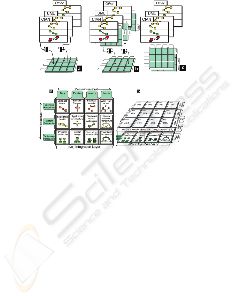
Figure 1: Layers of an interactive groupware system.
Figure 2: Integration layer structure and its relations with the Domain Specific Languages.
layers, notations layers -above- and integration
layers -below-. It is showed in Figure 1(c).
3.1 Integration Layer Definition
The integration layer we propose is based on the
Zachman Framework (Zachman 1987). This
Framework proposes a systematic taxonomy that
allows us associating concepts that describe the real
world with those who describe their information
system and its subsequent implementation (Sowa
and Zachman 1992). This taxonomy is defined in
two dimensions organized in perspectives and views.
The intersection of views and perspectives leads to
12 Modeling cells, (Figure 2). Each cell provides a
container for models that address a particular
perspective and view.
A perspective is an architectural representation at
a specific abstraction level and represents a set of
logical or physical constraints that may affect the
development of a system at that level. We use only
the business model, system model and technology
model perspectives.
The concept of view, or abstraction, is a
mechanism used by designers to understand a
specific system aspect. A key issue in software
architectures (perspective) is the support to handle
different levels of abstraction. For example, the data
view provides information about system domain
model to be developed. On the other hand, the
function view includes models representations about
of processes and functions of the system. We use the
data, function, network and people views.
This classification by using perspectives enable
designers to establish independence between
different levels of abstraction, however, it is
necessary to have a solid architecture that allows its
subsequent integration. MDA (Model Driven
Architecture) (Miller and Mukerji. 2003) is an
architecture that promotes design guided by models
and, as can be seen in Figure 2(b), there is a
relationship between the perspectives and levels of
MDA. Frankel et al (Frankel, Harmon et al. 2003)
describe the mapping between Zachman Framework
and MDA.
3.2 Integration Layer Notations
Structure
MDA provides the conceptual structure for
specifying the notations or domain specific
languages (DSL) used in every cell in the integration
layer. Therefore, each one of these models of the
cells is related to their respective metamodel (DSL)
JOINING SOFTWARE TECHNOLOGIES - A Model Driven Approach for Interactive Groupware Application
Development
325
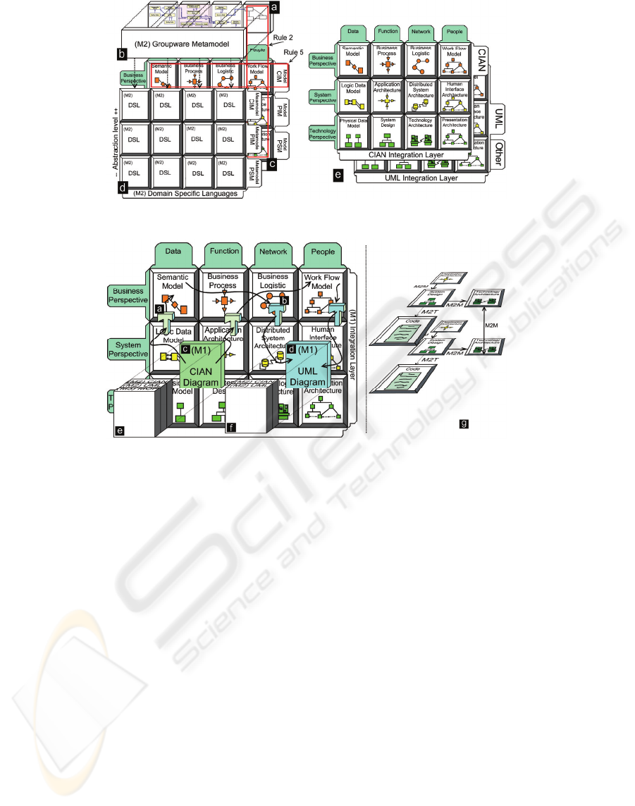
Figure 3: Domain Specific Languages Structure. Multiple integration layers example.
Figure 4: Integration between CIAM and UML. Model transformations.
Figure 2(b). All models into MDA are related due
they are based on a metamodel more abstract called
MOF (Meta Object Facility) (Miller and Mukerji.
2003). MOF facilitates the definition of the
necessary transformations to integrating models.
To obtain integrity, uniqueness, consistency and
recursion of the information specified, a series of
rules should be defined. Therefore, the seven rules
of the Zachman Framework has been adopted and
refined (Sowa and Zachman 1992). Examples of
these rules are: (R2) All of the cells in each column-
view-is guided by a single metamodel. (R5) The
composition or integration of all models of the cells
in a row is a complete model from this perspective.
(R7) The logic is recursive. Figure 3(c).
The information into integration layer cells must
be related to each other in two directions, views and
perspectives. Therefore, a base metamodel should be
specified (Figure 3(a)). This metamodel control the
models cells consistency into the same view -rule 2-
and it is necessary for the integration or composition
of the models into cells of the same row -rule 5 -
performing an integration role at perspective level. It
is possible to specify a base metamodel for each
integration layer, which depends on the nature of the
family of languages (DSL) that it is specifying. For
example, a single base metamodel can be used to
define common information useful for integration of
models in UML and CIAN.
3.3 Layer Integration Process
Multiple integration layers can coexist on a system. -
See Figure 3(e) -. This represents a new dimension,
which are defined for grouping integration layers
needed in an interactive groupware system. The
integration between these layers is performed
through transformations defined for each notation.
MDD proposes model transformations to reduce
the complexity of software design (Frankel 2004;
Jouault and Kurtev 2006). The integration of models
in UML and CIAN is done through an integration
layer; see Figure 4(left). The integration layer is
populated by using transformations applied to CIAN
models; see Figure 4(a). The structure of notations is
represented by some boxes containing metamodels
at M2 and M3 levels. Figure 4(e,f). The cell that
contain the CIAN diagram –Inter_Action- lies in the
level M1 (Model); in addition, the notation CIAN
which is defined as a UML Profile lies in the level
ICSOFT 2008 - International Conference on Software and Data Technologies
326
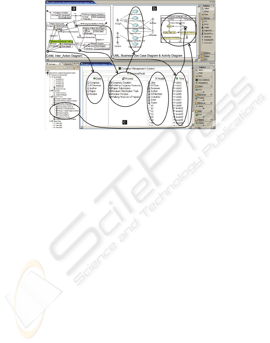
Figure 5: Integration example between CIAN and UML by using the CIAT tool.
M2 (metamodel). The transformations have as
input metamodel to CIAN and as output metamodel
the DSL defined for these cells. In Figure 4 (b) the
process to transform models from the integration
layer to generate UML diagrams is shown. It is not
always possible to obtain complete UML diagrams;
therefore, the generated information serves as a
starting point for the subsequent modeling in UML.
The transformation and integration process is
controlled through the integration layer metamodel.
The first transformation uses the CIAN metamodel
as the input metamodel and the integration layer
metamodel as the output metamodel. The second
transformation uses the integration layer metamodel
as the input metamodel and the UML metamodel as
the output metamodel. CIAT recognizes these three
metamodels and it is possible to edit models using
editors for each one of these.
The ATLAS Transformation Language (ATL) is
used to implement transformations between models.
We used the ATL plug-in for eclipse.
4 CASE STUDY (THE
CONGRESSES MANAGEMENT
SYSTEM)
We tried to develop a system for the management of
congresses. This example has been chosen because it
is referenced in the literature and it is used in several
approaches (Carlsen 1998; Trætteberg 2002). The
modeling process follows the stages shown in the
section 2. In this section a brief example of the
application of this method for integrating CIAN and
UML using CIAT is presented.
CIAT (Collaborative Interactive Applications Tool),
is a software tool based on models supporting
designers and engineers to create based models on
CIAN notation. This software tool supports the
interface design of groupware applications enabling
integration with software processes through UML
notation. The Eclipse Framework provides tools for
guiding the software modeling by using metamodel
concepts (Moore, Dean et al. 2004). We use the
EMF (Eclipse Modeling Framework) and GMF
(Graphical Editing Framework), to design the CIAT
tool as an Eclipse Plug-in.). We introduce CIAT and
their functionality is presented by mean of a case of
study, The Congress Management System.
The diagrams integration is made in the same
form as shown in Figure 4. This process is shown in
the Figure 5. In this example we only use the
business model perspective in the integration layer,
it is presented in Figure 5(c), which has complete
information for data views, function, network and
people. This information is generated from several
diagrams in CIAN. The Inter_action Diagram is
shown in Figure 5(a).
4.1 Sociogram Stage
Although this paper does not show the sociogram,
we have the following roles: PC-Chair, PCMember,
Reviewer, Author and Co-Author. The information
regarding the roles and relationships among
JOINING SOFTWARE TECHNOLOGIES - A Model Driven Approach for Interactive Groupware Application
Development
327
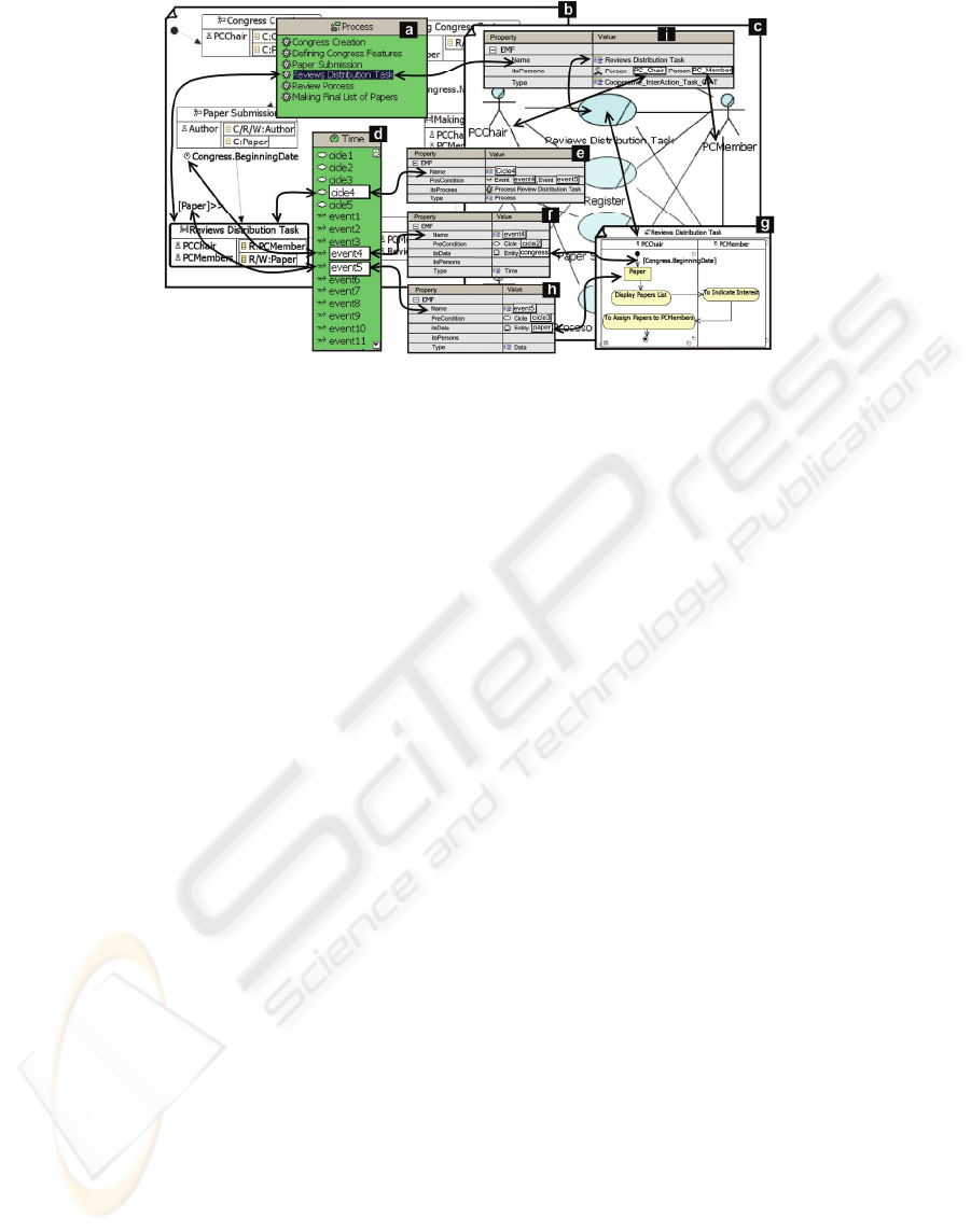
Figure 6: Detailed integration example between CIAN and UML.
organization members is processed through the
transformations to generate partial information of
Business Model and System Model perspectives.
This information is classified into these two
perspectives for the people view mainly. See column
people in Figure 5(b).
4.2 Group-Work Tasks Modeling Stage
In this phase we identify group task (collaborative or
cooperative) and the relationships in order to specify
group work. CIAM defines the cooperative tasks and
the collaborative task in a differentiated way. The
Inter_Action diagram, see Figure 5(a), illustrates the
system macro activities and their interdependencies.
This model is essential, because provides
information about the preconditions, post conditions,
messages and data that are required or generated by
the activities. UML lacks a diagram of this type.
The mapping between the use cases and the task
models can be based on the following basic
transformations (Lu, Paris et al. 1999): (a) The use
cases represent the highest levels of abstraction in
the hierarchical task models. (b) The “uses” relations
can be interpreted as temporal order expressions (in
particular a sequence connection). (c) The “extends”
relations indicate optional behaviors. This situation
can also be specified in a task model. (d) Temporal
dependencies are related to post conditions and
preconditions in activities diagram.
The Inter_Action diagrams are very rich in
information to populate the integration layer. The
Figure 5(c) illustrates the information extracted from
this diagram. The transformations separate
information as follows: (a) The Inter-Action
activities are associated with business use cases. The
cooperative activities are transformed into diagrams
activity. (b) The interdependencies are associated
with preconditions, post conditions and events
among various activity diagrams. (c) The domain
objects are associated with business entities. A
business object diagram is derived from the
information in each activity, which is related with
roles and objects.
4.3 Detailed Description of the
Integration
The Figure 5 shows a possible integration scenario
between CIAN diagrams and UML diagrams. In this
scenario we need to define the business use case
diagram that is related with the inter_action diagram.
A transformation generates the business use cases
diagram -Figure 6(c)- and the activity diagram -
Figure 6(g)- from Inter_action diagram mainly -
Figure 6(b). The integration is based on information
from the column process (function) -Figure 6(a)- and
the column time -Figure 6(d)- into the integration
layer. The variables cicle4, event4 and event5 have
the information needed to build these diagrams in
UML. See Figure 6(e,f,h), respectively. The
structure of these variables is defined in the
integration layer metamodel.
The variables of type event become preconditions
or postconditions of business use cases. In Figure
6(g) is observed as the event4 and event5 are
transformed into the guard
[Congress.Beginning.Date] and the object node
"Paper". Similarly, the variable “Reviews
Distribution task”, Figure 6(a), stores the
information required to relate the business use case
with their respective Actors - Figure 6(i).
ICSOFT 2008 - International Conference on Software and Data Technologies
328

ACKNOWLEDGEMENTS
This work has been supported by Universidad del
Quindío,d Castilla–La Mancha University and Junta
de Comunidades de Castilla–La Mancha in the
projects AULA-T (PBI08-0069), mGUIDE (PBC08-
0006-512) and M-CUIDE (TC20080552).
5 CONCLUSIONS
In this paper we have shown a brief picture of our
methodological proposal and the integration
proposal of models in CIAM and UML. We have
introduced our methodological approach to deal with
the conceptual design of applications for supporting
work in group, called CIAM. This approach is
organized in several stages in which conceptual
models are created using the CIAN notation.
We have used CIAT, a model-based software tool
that enables a user-centered approach for Model
Based User Interface Development of Collaborative
Applications. CIAT is intended for supporting as
early design cycle of a user interface, as the
integration with the software engineering process. It
allows stakeholders to construct models without
losing touch with the others ones, because each
stakeholder has a support for designing artifacts in
their specific domain.
We have used a study case in order to explain the
integration method by using an integration layer. A
taxonomy has been useful for integrating model
elements from CIAN toward UML by using an
integration layer. Finally, thanks to the use of GMF,
CIAT can integrate with other tools and services
available in Eclipse project.
REFERENCES
Carlsen, S. (1998). Action Port Model: A Mixed Paradigm
Conceptual Workflow Modeling Language.
Proceedings of the 3rd IFCIS International Conference
on Cooperative Information Systems.
Frankel, D. S. (2004) "An MDA Manifesto." MDA
Journal Volume, DOI:
Frankel, D. S., P. Harmon, et al. (2003) "The Zachman
Framework and the OMG's Model Driven
Architecture." MDA Journal Volume, DOI:
Gutwin, C. and S. Greenberg (1998). Design for
Individuals, Design for Groups: Tradeoffs between
power and workspace awareness. ACM CSCW’98,
Seattle, ACM Press.
IBM_Rational (2003). Too Navigator (Rational Unified
Process).
Jouault, F. and I. Kurtev (2006). On the architectural
alignment of ATL and QVT Proceedings of the 2006
ACM symposium on Applied computing, Dijon,
France ACM.
Lu, S., C. Paris, et al. (1999). Towards the automatic
generation of task models from object oriented
diagrams. In Engineering for Human-Computer
Interaction. Boston, Kluwer academic publishers.
Miller, J. and J. Mukerji. (2003). "MDA Guide Version
1.0.1." 08-07-2007, from
http://www.appdevadvisor.co.uk/express/vendor/doma
in.html.
Molina, A. I., M. A. Redondo, et al. (2006). A conceptual
and methodological framework for modeling
interactive groupware applications. 12th International
Workshop on Groupware (CRIWG 2006), Valladolid.
Spain, Springer-Verlag (LNCS).
Molina, A. I., M. A. Redondo, et al. (2006c). A conceptual
and methodological framework for modeling
interactive groupware applications. 12th International
Workshop on Groupware (CRIWG 2006), Valladolid.
Spain, Springer-Verlag (LNCS).
Molina, A. I., M. A. Redondo, et al. (2007). "CIAM: A
methodology for the development of groupware user
interfaces." Journal of Universal Computer
Science(JUCS).
Moore, B., D. Dean, et al. (2004). Eclipse Development
using the Graphical Editing Framework and the
Eclipse Modeling Framework, ibm.com/redbooks.
Paternò, F. (2004). ConcurTaskTrees: An Engineered
Notation for Task Models. The Handbook Of Task
Analysis For HCI.
Paternò, F., C. Mancini, et al. (1997). ConcurTaskTree: A
diagrammatic notation for specifying task models.
IFIP TC 13 International Conference on Human-
Computer Interaction Interact'97, Sydney, Kluwer
Academic Publishers.
Sowa, J. F. and J. A. Zachman (1992). "Extending and
formalizing the framework for information systems
architecture " IBM Syst. J: 590-616
Trætteberg, H. (2002). Model-based User Interface
Design. Department of Computer and Information
Sciences, Norwegian University of Science and
Technology. doctorade: 211.
Welie, M. v. and G. v. d. Veer (2003). Groupware Task
Analysis. Handbook Of Cognitive Task Design.
Zachman, J. A. (1987). "A Framework For Information
Systems Architecture." IBM Ssystems Journal 26(3).
JOINING SOFTWARE TECHNOLOGIES - A Model Driven Approach for Interactive Groupware Application
Development
329
