
CONFIGURATION FRAGMENTS AS THE DNA OF SYSTEM
AND CHANGE PROPERTIES
Architectural Change of Component-based and Service-oriented Systems
D’Arcy Walsh
Bedarra Research Labs, Ottawa, Ontario, Canada
Keywords: Constraint-based systems, Component-based systems, Dynamic reconfiguration, Service-oriented
architecture, Software evolution, and System integrity.
Abstract: The concept of a Configuration Fragment is adopted to help address the challenge of managing the different
kinds of dependencies that exist during the evolution of component-based and service-oriented systems.
Based upon a model of Architectural Change and an example of an application-specific context,
Configuration Fragments are defined in order to express and reconcile change properties with respect to
existing system properties. During system evolution, Configuration Fragments enable the configuration of
Service and Service Protocol, Operation and Provided Service, Operation and Required Service, Operation
and Operation, Operation and State Element, Operation and Composite Component, Component and
Component, and Required Service and Provided Service dependencies. This occurs through configuration
leading to association, disassociation, or refinement of these system elements.
1 INTRODUCTION
As deployed software-intensive systems become
increasingly prevalent and interdependent within
application specific contexts, managing change as
these systems evolve is becoming increasingly
critical. Since applications are rarely introduced,
reconfigured, or decommissioned in complete
isolation, a major problem is the management of
system dependencies.
To enable a systematic response to the problem
of dependency management, this paper identifies
different kinds of configuration information and
presents a technique for applying this information
that is illustrated using a application specific context
which demonstrates the generality of the approach.
To do this, a system model is adopted that is
composed of system elements which support the
component-based and service-oriented computing
paradigm. The system elements are used to define
different kinds of behavioural and structural
dependencies which must be managed when desired
system properties change over time. Specific kinds
of configuration information are defined based upon
these different kinds of dependencies. The approach
for applying this information is based upon a model
of architectural change of software-intensive
systems (Walsh et al 2007 and Walsh et al 2008).
The following are representative examples of
related research.
(Crevantes et al 2003) investigates implementing
dynamic availability within a service-oriented
component model. By adopting the Open Services
Gateway Initiative (OSGi 2007) as an
implementation platform, they investigate
component-to-service and service-to-service system
dependencies. Separately noted, based on these
dependencies, the Spring Framework (Spring 2007)
can be adopted to augment any OSGi-based
implementation when a Spring application context
injects behaviour to further configure OSGi
provisioned services (deployed as bundles). By
identifying a more complete set of system
dependencies, this paper is effectively a super-set of
this approach; it also specifies a model of
architectural change that unifies the application of
change types.
(Felfernig et al 2007) address the complexity of
dependency management through the formulation of
a domain model that enables the construction of
complex software configurations for executable
configuration, for example through generative
constraint satisfaction (Fleischanderl et al 1998).
Research on the dynamic constraint satisfaction
problem (CSP) is viewed to provide more precise
semantics for the model of architectural change
270
Walsh D. (2008).
CONFIGURATION FRAGMENTS AS THE DNA OF SYSTEM AND CHANGE PROPERTIES - Architectural Change of Component-based and
Service-oriented Systems.
In Proceedings of the Tenth International Conference on Enterprise Information Systems - DISI, pages 270-275
DOI: 10.5220/0001704602700275
Copyright
c
SciTePress

presented in this paper when global and local change
properties are reconciled with existing system
properties.
(Lestideau et al 2002) specify a model of the
software deployment process and unifies this with a
component model towards the automated
configuration and deployment of software-intensive
systems. Using a more refined model of components
that implement services, this paper links the
deployment process to relevant system elements
based upon different kinds of system dependencies
that apply with respect to the refined model.
(Sangal et al 2005) define a process for
managing dependencies based on a Dependency
Structure Matrix (DSM) that is directly extracted
from the implementation of a software-intensive
system. As an underlying model of dependency
(represented as a partitioned adjacency matrix), the
DSM approach is viewed as a useful technique for
partially representing existing system properties and
their reconciliation with contemplated change
properties. This paper presents more refined notions
of dependence and the role they play based on a
general model of architectural change and the
different dependency categories that cover
architectural change.
Informed by related research, this paper relates
specific kinds of configuration information with
desired system properties (called change properties)
and then augments configuration information that is
associated with existing system properties. A major
implication is that informal expressions of desired
change can be decomposed as fragments of
configuration information that are defined in terms
of system model elements. Depending on the
application-specific context, the fragments of
configuration information may potentially be shared
when decomposing the expression of more than one
change property.
Using a motivating example that provides an
application-specific context, the paper provides a
description of Configuration Fragments and
illustrates their role during the evolution of a
software-intensive system using the application-
specific context.
2 MOTIVATING EXAMPLE
The following is a review of a financial analysis
system case study more fully reported on in (Walsh
et al 2007). The case study is an application-specific
example of changing global and local properties
leading to comprehensive change. The example
describes the components and the dynamic
interoperation of two initially decoupled financial
systems that specialize in maintaining knowledge
and providing predictions about a particular sector of
the economy. System A’s clients are concerned with
shorter-term predictions. System B’s clients are
concerned with longer-term predictions.
Figure 1 shows the original control style of
System A. Use Case Maps (UCMs) (Buhr and
Casselman 1996) are used to illustrate the causal
flow that is required of System A’ s components to
provide shorter-term predictions. For example, for
reason of timeliness, cash flow projections and
valuation assessment are done on-line.
Figure 1: Original Control Style of System A.
System A’s responsibilities are: (a1) generate on-
line financial conditions, (a2) provide cash flow
projections, (a3) provide valuation assessment, (a4)
update on-line financial conditions and update
knowledge information about market sector, (a5)
determine current market knowledge, (a6) current
financial conditions and market knowledge, (a7)
update preferred stock and common stock value
predictions, (a8) provide knowledge information
about market sector, and (a9) update knowledge
information about market sector.
Figure 2 shows the original control style of
System B. UCMs are used to illustrate the causal
flow that is required of System B’ s components to
provide longer-term predictions. For example, for
reason of accuracy, cash flow projections and
valuation assessment are done off-line on demand.
System B’s responsibilities are: (b1) generate on-
line financial conditions, (b2) update on-line
financial conditions and update knowledge
information about market sector, (b3) determine
current knowledge about market, (b4) provide
current financial conditions and knowledge about
market, (b5) determine cash flow projections, (b6)
provide cash flow projections, (b7) determine
valuation assessment, (b8) provide valuation
assessment, (b9) update preferred stock and bond
value predictions, (b10) provide knowledge
information about market sector, and (b11) update
knowledge information about market sector.
The following are examples of global system
properties:
• (GP1) The control style of each system (as
depicted by use case maps );
Scenario
Ana lys is
Energy Sector
Knowledge
Energy Sector
Conditions
Valuation AssessmentCash Flow Projections
a1
a2
a3
a4
a5
a6
a7
a8
a9
CONFIGURATION FRAGMENTS AS THE DNA OF SYSTEM AND CHANGE PROPERTIES - Architectural Change
of Component-based and Service-oriented Systems
271

Figure 2: Original Control Style of System B.
• (GP2) The operations of different components
provide needed behaviour within limited time
constraints (scenario analysis must not be
invalidated by current financial conditions); and
• (GP3) The state elements of different
components are updated in a synchronized fashion
(present value analysis, cash flow projection, and
scenario analysis reference data is synchronized).
The following are examples of local system
properties:
• (LP1) A component has an upper bound on the
number of threads that may be spawned in response
to remote service requests;
• (LP2) A provided service has at most one
required service bound to it and vice versa; and
• (LP3) The values of certain state elements may
not change (Scenario Analysis reference data, once
synchronized, remains immutable).
The systems are dynamically reconfigured so that
System A can leverage System B’s preferred stock
predictions. To do this, each system’s architectural
constraints are reconciled and changes are
constrained to be backward compatible. System A is
then able to provide improved analytic results for its
clients based upon the new information that is
available from System B.
In this example, an Architectural Change means
the Scenario Analysis components of each system
dynamically evolve in order to inter-operate. This is
represented as a change to GP1 as shown by Figure
3. Global and local consistency management must
ensure the integrity of GP1 to GP3 and LP1 to LP3,
respectively, to maintain the consistency of each
system in the face of change.
Figure 3 shows the new control style of System
A. A new UCM represents the causal flow linking
the Scenario Analysis component of System A to the
Scenario Analysis component of System B. This
enables System A to use System B’s longer-term
predictions to validate its shorter-term predictions.
The new responsibilities are: (a10) Determine
Long-Term Predicted Values, (a11) Provide Long-
Term Predicted Values, and (a12) Validate Short-
Term Predictions using Long-Term Predictions.
Figure 3: New Control Style of System A.
With change localized to the scenario analysis
components of both systems, system evolution
happens as follows:
• A communication path is established between
the scenario analysis components;
• System A’s external interactions evolve to
support a new required service;
• System B’s external interactions evolve to
support a new provided service;
• Internal behaviour of System A’s scenario
analysis component evolves to process the new
information that is provided by System B; and
• Internal behaviour of System B’s scenario
analysis component evolves to provide the new
information to System A.
3 CONFIGURATION FRAGMENT
Consider any kind of dependency which configures
system element A with respect to system element B,
with the kinds of system elements possible defined
by the computing paradigm that is adopted. In
general, a Configuration Fragment (CF) associates A
with B, disassociates A from B, or refines an
existing association between A and B. This is
referred to as configuration leading to association,
configuration leading to disassociation, or
configuration leading to refinement respectively.
When associating A with B, in addition to A
becoming dependent upon B, A, B, or both A and B
may not yet exist. During configuration leading to
association, any system model element that does not
yet exist is instantiated when its CF is activated.
Instantiation occurs when a system’s signature is
regenerated. In addition, any system model element
that does exist may be realigned. This also occurs
when a system’s signature is regenerated.
When disassociating A from B, in addition to A
no longer being dependent upon B, A, B, or both A
and B may no longer be needed and therefore may
be deactivated from the system as a whole. In
addition, during configuration leading to
disassociation, any system element that is not
deactivated may be realigned. Deactivation or
Scenario
Analysis
Energy Sector
Knowledge
Energy Sector
Conditions
Valuation
Assessment
Cash Flow
Projections
b1 b2
b3
b4
b5
b6
b7
b8
b9
b10
b11
Scenario Analysis-A
Energy
Sector
Knowledge-A
a5
a6
a12
Scenario
Analysis-B
a7
a10
a8
a11
a9
ICEIS 2008 - International Conference on Enterprise Information Systems
272

realignment occurs when a system’s signature is
regenerated.
When refining an existing association between A
and B, in addition to A remaining dependent upon B,
A, B, or both A and B may be realigned. During
configuration leading to refinement, both system
elements already exist and one or both elements are
realigned when a system’s signature is regenerated.
A CF is effectively a fragment of the signature of
a system that is associated with a particular global or
local property. The context and related
characteristics of the activation, realignment, or
deactivation of a system element are set by the
system or change property which the CF partially
represents as configuration information. If a
particular CF is compatible with and can be
reconciled among more than one global or local
property it may be shared among those properties,
otherwise the CF is not shared and therefore unique
to a particular property. Shared CFs are viewed to be
more primitive units of configuration information
that are used as building blocks of more complex
CFs that in turn conform to the context of particular
system or change properties.
The kinds of CFs are based upon the kinds of
dependencies that can determine a system’s
behavioural or structural configuration. What
follows is a description of each kind of configuration
and the particular system elements that are activated,
realigned, or deactivated when that kind of
configuration happens. The next section provides an
application-specific example of CFs for the case
study presented in Section 2.
A Behavioural Configuration Fragment (BCF) is
information pertaining to:
• Service and Service Protocol Configuration
when Service and Service Protocol system elements
dependencies change;
•
Operation and Required Service
Configuration when Operation and Required Service
system elements dependencies change;
• Operation and Provided Service
Configuration when Operation and Provided Service
system elements dependencies change;
•
Operation and Operation Configuration
when Operation system elements dependencies
change;
• Operation and State Element Configuration
when Operation and State Element system elements
dependencies change; or
• Operation and Composite Component
Configuration, when Operation and Composite
Component system elements dependencies change.
A Structural Configuration Fragment (SCF) is
information pertaining to:
• Component and Component Configuration
when Component system elements dependencies
change; or
• Required Service and Provided Service
Configuration when Required Service and Provided
Service system elements dependencies change.
4 CONFIGURATION
FRAGMENTS AND SYSTEM
EVOLUTION
What follows is a description of the role of CFs
during Architectural Change as described in (Walsh
et al 2007). Figure 3 shows a new UCM linking the
Scenario Analysis component of System A with the
Scenario Analysis component of System B, which
sets the specific context for this section.
Because this is an example of configuration
leading to association, system elements are either
activated or realigned. Extending the example to
remove the UCM after System A interacts with
System B would be a way to demonstrate
configuration leading to disassociation and therefore
deactivation.
In this example, system evolution is manifested
as a change property that augments the control style
of each system. It will be referred to as Augmented-
GP-1. The outcome is a change to the current control
style of each system represented by an update to GP-
1 through GP-1's reconciliation with Augmented-
GP-1.
The process of Architectural Change is
manifested as follows:
4.1 Emergent Change Property
Augmented-GP-1 represents an emergent change
property which informally stated is "Augment the
control styles of each system so that System A can
leverage System B’s preferred stock predictions".
Figure 4 shows the CFs that defines the specific
configuration information of Augmented-GP-1.
CF1 is required to satisfy all new
responsibilities; CF2 is required to satisfy
responsibilities (a10) and (a11); CF3 is required to
satisfy responsibility (a10); CF4 is required to
satisfy responsibility (a11); CF5 is required to
satisfy responsibilities (a10) and (a12); CF6 is
required to satisfy responsibility (a11); and CF7 is
required to satisfy responsibility (a11).
CONFIGURATION FRAGMENTS AS THE DNA OF SYSTEM AND CHANGE PROPERTIES - Architectural Change
of Component-based and Service-oriented Systems
273
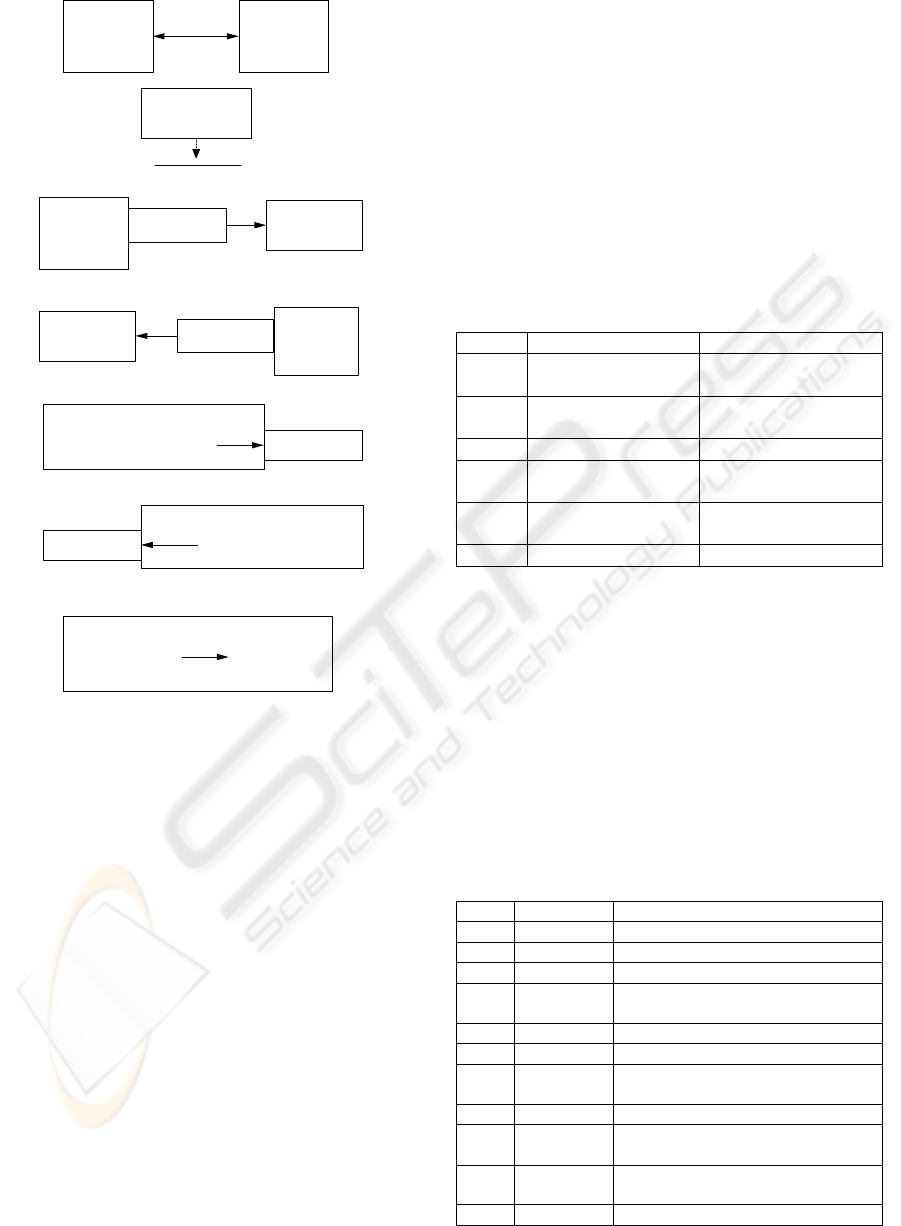
CF1 (Component to Component Configuration)
CF2 (Required Service to Provided Service Configuration)
CF3 (Service to Service Protocol Configuration)
CF4 (Service to Service Protocol Configuration)
CF5 (Operation to Required Service Configuration)
CF6 (Operation to Provided Service Configuration)
CF7 (Operation to State Element Configuration)
Scenario
Analysis
System A
Component
Scenario
Analysis
System B
Component
Activated
Connection
Activated
Connection
'short-term
predictions for long-
term predictions'
Service Protocol
Scenario
Analysis
System A
Component
'short-term
predictions'
Required Service
'short-term
predictions for
long-term
predictions'
Service Protocol
Scenario
Analysis
System B
Component
'long-term
predictions'
Provided Service
'short-term
predictions for
long-term
predictions'
Service Protocol
Scenario Analysis System A
Component
'short-term
predictions'
Required Service
'generateShortTermPredictions()
Operation
Scenario Analysis System B
Component
'long-term
predictions'
Provided Service
longTermPredictions()
Operation
Scenario Analysis System B
Component
longTermPredictions()
Operation
LongTermPreferred
StockValues
State Element
Figure 4: Augmented-GP-1.
4.2 Updated Systems Properties
Table 1 shows the effect of Architectural Change
when systems properties are updated. The existing
CFs of GP-1 for Systems A and B, which by
definition satisfy the existing control configurations
shown in Figures 1 and 2, are updated with the CFs
of Augmented-GP-1. CF1 and CF2 are added to the
GP-1 definitions for both systems and are therefore
shared between those definitions. CF3 and CF5 are
added to the GP-1 definition for System A. CF4,
CF6, and CF7 are added to the GP-1 definition for
System B.
When the respective GP-1 definitions are
updated, global consistency management ensures the
integrity of global properties. To ensure GP-2,
especially for System B, the new systems interaction
must not violate end-to-end performance constraints.
To ensure GP-3, no action is required because the
dependencies associated with the synchronization of
present value analysis, cash flow projection, and
scenario analysis reference data are not affected.
Local consistency management ensures the
integrity of local properties. To ensure LP-1, the
upper bound on the number of threads that may be
spawned in response to remote service requests for
the Scenario Analysis component of System B must
be respected. To ensure LP-2, there is just one
service binding linking System A and B. To ensure
LP-3, no action is required because the dependencies
associated with the immutability of Scenario
Analysis reference data are not affected.
Table 1: How Systems Properties are Updated.
System A System B
GP-1
CF1, CF2, CF3, &
CF5 are added
CF1, CF2, CF4, CF6,
& CF7 are added
GP-2
Global Consistency
Check
Global Consistency
Check
GP-3
Not Affected Not Affected
LP-1
Not Affected Local Consistency
Check
LP-2
Local Consistency
Check
Local Consistency
Check
LP-3
Not Affected Not Affected
4.3 Regenerated Systems Signatures
The process of Architectural Change is completed
when the system signatures of both systems are
regenerated. A regenerated system signature
manifests itself through follow-on types of change
that evolve the external interactions and internal
behavior of system components, which is described
in (Walsh et al 2007 and Walsh et al 2008). Table 2
shows the change effect of each CF when this
happens.
Table 2: Outcome of Regenerated Systems Signatures.
CF CF Action CF Change Effect
CF1 activates connection linking components
CF1 realigns Scenario Analysis System A
CF1 realigns Scenario Analysis System B
CF2 activates short-term predictions for long-
term predictions service protocol
CF2 realigns connection linking components
CF3 activates short-term predictions service
CF3 realigns short-term predictions for long-
term predictions service protocol
CF4 activates long-term predictions service
CF4 realigns short-term predictions for long-
term predictions service protocol
CF5 realigns generateShortTermPredictions()
operation
CF5 realigns short-term predictions service
ICEIS 2008 - International Conference on Enterprise Information Systems
274

Table 2: Outcome of Regenerated Systems Signatures
(cont.).
CF CF Action CF Change Effect
CF6 activates longTermPredictions() operation
CF6 realigns long-term predictions service
CF7 realigns longTermPredictions() operation
CF7 realigns LongTermPreferredStockValues
state element
5 SUMMARY AND FUTURE
WORK
This paper defines a CF to be a fragment of the
signature of a system that is associated with global
or local properties. The following kinds of CFs are
defined: Service and Service Protocol, Operation
and Required Service, Operation and Provided
Service, Operation and Operation, Operation and
State Element, Operation and Composite
Component, Component and Component, and
Required Service and Provided Service
configuration.
For each kind of CF, relevant system model
elements are activated, realigned, or deactivated
during configuration leading to association,
disassociation, or refinement when the CFs of
system properties are regenerated from the CFs of
change properties.
Future work will investigate:
• specific criteria that distinguish primitive
(building block) CFs from more complex CFs and
that distinguish reconciliation policies that apply
between change and system properties, including the
linkage among system or change property
expressions and global and local consistency
management;
• general composition (Clarke 2001) and
customized composition patterns when regenerating
a system’s signature; and
• satisfiability solvers to compute the
reconciliation of change and system properties
(Jackson 2002), including predicting the impact of
updated system properties prior to regenerating a
system’s signature.
REFERENCES
Buhr, R., Casselman, R., 1996. Use Case Maps for Object-
Oriented Systems. Prentice Hall. New York, New
York.
Cervantes, H., Hall, R.S., 2003. Automating Service
Dependency Management in a Service-Oriented
Component Model. In Proceedings of the 6th ICES
Workshop on Component-Based Engineering:
Automated Reasoning and Prediction. Carnegie
Mellon University, USA, and Monash University,
Australia. Portland, Oregon.
Clarke, S., 2001. Composition of Object-Oriented Design
Models. Ph.D. Thesis. Dublin City University. Dublin,
Ireland.
Felfernig, A., Friedrich, G., Jannach, D., Zanker, M.,
2007. Chapter 7: Rapid Knowledge Base Development
for Product Configuration Systems using the Unified
Modeling Language. In Domain Oriented System
Development. Taylor and Francis. London, England.
Fleischanderl, G., Friedrich, G.E., Haselbock, A.,
Schreiner, H., Stumptner, M, 1998. Configuring Large
Systems Using Generative Constraint Satisfaction. In
IEEE Intelligent Systems, Vol. 13, Issue 4. IEEE
Press. New York, New York.
Jackson, D., 2002. Micomodels of Software: Lightweight
Modelling and Analysis with Alloy. MIT Lab for
Computer Science. Cambrige, Mass.
Lestideau, V., Belkhatir, N., Cunin, P., 2002. Towards
automated software component configuration and
deployment. In Proceeding of 3rd International
Workshop on Process support for Distributed Team-
based Software Development (PDTSD'02).
International Institute of Informatics and Systemics.
Orlando, Florida.
Open Services Gateway Initiative, “OSGI Service
Platform Release”, Specification Release 4.1, May
2007.
Sangal, N., Jordan, E., Sinha, S., Jackon, D., 2005. Using
Dependency Models to Manage Complex Software
Architecture. In Proceedings of Object-Oriented
Programming Languages and Systems (OOPSLA)
2005. ACM Press. New York, New York.
Spring Framework Initiative, “Spring Framework”,
Specification Release 2.5, November 2007.
Walsh, D., Bordeleau, F., Selic, S., 2007. Domain analysis
of dynamic system reconfiguration. Software and
System Modeling, Volume 6, Number 4. DOI:
10.1007/s10270-006-0038-4, Springer-Verlag.
Walsh, D., Bordeleau, F., Selic, S., 2008. A Constraint-
Driven Executable Model of Dynamic System
Reconfiguration. Journal of Software, Volume 3, Issue
4. Academy Press.
CONFIGURATION FRAGMENTS AS THE DNA OF SYSTEM AND CHANGE PROPERTIES - Architectural Change
of Component-based and Service-oriented Systems
275
