
RECONFIGURATION OF EMBEDDED SYSTEMS
∗
Mohamed Khalgui, Martin Hirsch, Dirk Missal and Hans-Michael Hanisch
Martin Luther University, Halle, Germany
Keywords:
Industrial Embedded Systems, IEC61499 Function Blocks, Reconfiguration, Model-checking.
Abstract:
This paper deals with automatic reconfiguration of embedded systems following the Component-based Stan-
dard IEC61499. First of all, we propose a new reconfiguration semantic allowing the improvement of the
system performance even if there is no hardware fault. In addition, we characterize all possible reconfigura-
tion forms in order to cover all possible execution scenarios and to apply an automatic reconfiguration, we
define thereafter an agent-based architecture that we model with nested state machines to control the design
complexity.
1 INTRODUCTION
Nowadays, the new generation of industrial control
systems is addressing new criteria as flexibility and
agility. To reduce their cost, these systems have to
be changed and adapted to their environment with-
out any disturbance. Several academic and industrial
research works have been made to develop reconfig-
urable systems. We distinguish in these works two
reconfiguration policies: the static and dynamic re-
configurations. The static reconfiguration is applied
off-line to apply changes before the system cold start
(Angelovet al., 2005), whereas the dynamicreconfig-
uration is applied dynamically at run-time. In the last
policy, two cases exist: the manual reconfiguration
applied by the user (Rooker et al., 2007) and the auto-
matic reconfiguration applied by an intelligent agent
localized in the system (Al-Safi and Vyatkin, 2007).
In this paper, we are interested in the automatic
reconfiguration of industrial control systems which
have to satisfy according to user requirements func-
tional and temporal properties but their time to mar-
ket has to be shorter than ever. To satisfy all these
requirements,we use thecomponent-basedmethodol-
ogy supporting the modularity as well as the reusabil-
ity of already developed components. Today, sev-
eral rich technologies have been proposed to develop
component-based manufacturing systems and among
∗
This work is supported by the Humboldt foundation in
Germany under the reference TUN1127196STP.
all these technologies, the standard IEC61499 is pro-
posed by the International Electrotechnical Commis-
sion (IEC) to design the application as well as the cor-
respondingexecutionenvironment. A FunctionBlock
(FB) is a unit of software supporting functionalities
of an application and it is composed of an interface
and an implementation where the interface contains
data/event inputs and outputs supporting interactions
with the environment. Events are responsible for the
activation of the block while data contain valued in-
formation. The implementation contains algorithms
to execute when the corresponding events occur. The
selection of an algorithm to execute is performed by
a state machine called the Execution Control Chart
(ECC). The ECC is also responsible for sending out-
put events at the end of the algorithm execution. A
control application is specified by a network of FBs
such as each event input (resp. output) of a block
is linked to an event output (resp. input) by a chan-
nel and it corresponds otherwise to a global input
(resp. output). Data inputs and outputs follow the
same rules. Today, several research works on this
standard have been proposed (Khalgui and Thram-
boulidis, 2008), rich tools
2
and several industrial
platforms
3
have been developed while following this
standard.
In this paper, we aim to develop reconfigurable
IEC61499 control systems. Several research works
2
http://www.isagraf.com, http://www.holobloc.com
3
www.itia.cnr.it
157
Khalgui M., Hirsch M., Missal D. and Hanisch H. (2008).
RECONFIGURATION OF EMBEDDED SYSTEMS.
In Proceedings of the Fifth International Conference on Informatics in Control, Automation and Robotics - ICSO, pages 157-162
DOI: 10.5220/0001487001570162
Copyright
c
SciTePress

dealing with the reconfigurationof these systems have
been proposed (Angelov et al., 2005; Rooker et al.,
2007; Al-Safi and Vyatkin, 2007) but they are limited
to particular cases (e.g. to resolve hardware faults or
to add new functionalities like the update of an al-
gorithm in a block) and they do not address all the
reconfiguration reasons that can possibly occur in in-
dustry. We define a new semantic of the reconfigura-
tion to improve th e system performance even if there
is no hardware fault and we characterize all possi-
ble reconfiguration forms that we can apply on a sys-
tem. To apply an automatic reconfiguration at run-
time, we propose thereafter an agent-based architec-
ture to handle reconfiguration scenarios bringing the
system into safe states. We model the agent accord-
ing to well suited formal formalism: the Net Con -
dition/Event Systems (denoted NCES) proposed by
Rausch and Hanisch in (Rausch and Hanisch, 1995).
We present in the next section the NCES formal-
ism and in Section3 the EnAS production system to
be used as an example in the paper. We define in Sec-
tion4 a new semantic of the reconfiguration before
we detail in Section5 all reconfiguration forms. Fi-
nally before conclusions, we present in Section6 the
Agent-based architecture to handle automatic recon-
figurations.
2 NCES FORMALISM
The formalism of Net Condition/Event Systems
(NCES) is an extension of the well k nown Petri net
formalism. It was introduced by Rausch and Hanisch
in (Rausch and Hanisch, 1995) and further developed
through the last years according to which a NCES is
a place-transition net formally represented by a tuple:
NCES =(P,T,F,CN ,EN,C
in
,E
in
,C
out
,E
out
,
B
c
,B
e
,C
s
,D
t
,m
0
) where,
(1) P (resp, T) is a non-empty finite set of places
(resp, transitions), (2) F is the set of flow arcs, F :
(PXT)
(TXP),(3)CN (resp, EN) is the set of con-
dition (resp, event) arcs, CN ⊆ (PXT) (resp, EN ⊆
(TXT)), (4) C
in
(resp, E
in
) is the set of condition
(resp, event) inputs, (5) C
out
(resp, E
out
)isthesetof
condition (resp, event) outputs, (6) B
c
(resp, B
e
)isthe
set of condition (resp, event) input arcs in a NCES
module, (7) B
c
⊆ (C
in
XT) (resp, B
e
⊆ (E
in
XT)), (8)
Cs (resp, Dt) is the set of condition (resp, event) out-
put arcs, (9) Cs ⊆ (PXE
out
) (resp, Dt ⊆ (TXE
out
)),
(10) m
0
: P → 0,1 is the initial marking.
The semantics of NCES are defined by the firing
rules of transitions. There are several conditions to be
fulfilled to enable a transition to fire. First, as it is in
ordinary Petri nets, an enabled transition has to have a
token concession. That means that all pre-places have
to be marked with at least one token . In addition to the
flow arcs from places, a transition in NCES may have
incoming condition arcs from places and event arcs
from other transitions. A transition is enabled by con-
dition signals if all source places of the condition sig-
nals are marked by at least one token. The other type
of influence on the firing can be described by event
signals which come to the transition from some other
transitions. Transitionshaving no incoming eventarcs
are called spontaneous,otherwiseforced. A forced
transition is enabled if it has token concession and it
is enabled by condition and event signals (Rausch and
Hanisch, 1995).
We note fin ally that the model-checker SESA is a
useful tool to verify functional and temporal proper-
ties on NCES (Rausch and Hanisch, 1995). We apply
it in our work to verify reconfigurablecontrol systems
following the standard IEC 61499.
3 INDUSTRIAL CASE STUDY
In this paper, we are interested in the manufactur-
ing system EnAS used as a demonstrator at the Mar-
tin Luther University of Halle (in Germany). This
system is implemented while f ollowing the standard
IEC61499 and it allows the transportation of pieces
from the production into storing units. The pieces
shall be placed inside tins to close with caps after-
wards
4
. Two different production strategies can be
applied : we place in each tin one or two pieces ac-
cording to production rates of pieces, tins and caps.
In this paper, we denote respectively by nb
pieces
,
nb
tins+caps
the production number of pieces, tins (as
well as caps) per hour. In the following, we denote
by Threshold a variable ( defined in specifications) al-
lowing to choose the adequate production strategy.
The EnAS system is mainly composed of a belt,
two Jack stations (J
1
and J
2
) and two Gripper stations
(G
1
and G
2
) (Figure 1). The Jack stations place new
produced pieces and to close tins with caps, whereas
the Gripper stations remove charged tins from the belt
into the storing units.
Initially, the be lt m oves a particular pallet contain-
ing a tin and a cap into the first Jack station J
1
.Ac-
cording to the production parameters, we distinguish
two cases,
4
For d etailed information on the EnAS system, we re-
fer the reader to our group website: http://at.informatik.uni-
halle.de
ICINCO 2008 - International Conference on Informatics in Control, Automation and Robotics
158

Figure 1: Distribution of the EnAS stations.
• The First Production Policy
(nb
pieces
/nb
tins+caps
≤ Threshold): the Jack
station J
1
places from the production station a
new piece and closes the tin with the cap. In this
case, the Gripper station G
1
removes the tin from
the belt into the storing station St
1
.
• The Second Production Policy
(nb
pieces
/nb
tins+caps
> Threshold): the Jack
station J
1
places just a piece in the tin which is
moved thereafter into the second Jack station to
place a second new piece. Once J
2
closes the
tin with a cap, the belt moves the pallet into the
Gripper station G
2
to remove the tin (with two
pieces) into the second storing station St
2
.Ifwe
follow this policy, the productivity as well as the
factory receipt is improved.
4 NEW RECONFIGURATION
SEMANTIC
We define in this paper the reconfiguration semantic
as follows.
Definition. A dynamic reconfiguration is any
change according to well-defined conditions in the
software as well as in the hardware components to
lead the system into a better safe state at run-time.
According to the standard IEC61499, we mean in this
definition by a change in the software components
any operation allowing to add, to remove or to update
Function Blocks to improve the behavior of all the
system. On the other hand, we mean by a change in
the hardware components any operation allowing to
add, remove or update devices used in the execution
environment.
Running Example. In the EnAS system, we
apply the reconfiguration for two reasons: (i) to
save the system when hardware p roblems occur at
run-time. For example, when the Gripper G2 is
broken, then we have only to follow the first pro-
duction policy by placing only one piece in each
tin. (ii) to improve the production gain when
(nb
pieces
/nb
tins+caps
> Threshold). In this case, we
have to apply the second policy to improve the factory
receipt. Therefore, we have to apply changes in the
systemarchitecture and blocks to followthispolicy. In
this example, the reconfiguration is not only applied
to resolve hardware problems as proposed in (Al-Safi
and Vyatkin, 2007)but alsoto improve the system per-
formance by increasingthe production gain. This new
semantic of the reconfiguration concept will be a fu-
ture issue in the manufacturing industry.
5 RECONFIGURATION CASES
We classify in this section all reconfiguration forms to
possibly apply on a control system in order to cover
all possible reasons described above. We distinguish
the following forms:
• First Form. It deals with the change of the
application architecture that we consider as a
composition of Function Blocks. In this case,
we have possibly to add, to remove or also to
change the localization of Function Blocks (from
one to another device). This reconfiguration form
requires to load new (or to unload old, resp)
blocks in (from, resp) the memory.
Running Example. We distinguish in EnAS two
architectures: (i) We implement the system with
the first architecture when we follow the first
production policy. In this case, we load in the
memory the Function Blocks J1
CTL, Belt CTL
and G1
CTL. (ii) We implement the system
with the second architecture when we follow
the second production policy. In this case, we
load in the memory the Function Blocks J1
CTL,
J2
CTL, Belt CTL and G2 CTL. If we follow
the first production policy and nb
pieces
/nb
tins+caps
becomes higher than Threshold, then we have to
load the function block G2
CTL in the memory to
follow the second production policy.
• Second Form. it deals with the reconfiguration of
the application without changing its architecture
(e.g. without loading or unloading Function
Blocks). In this case, we apply changes on the
internal structure o f blocks or on their composi-
tion as follows: (a) we change the ECC structure,
(b) we add, update or remove data/events in-
puts/outputs, (c) we update algorithms, (d) we
RECONFIGURATION OF EMBEDDED SYSTEMS
159

change the configuration of connections between
blocks.
Running Example. In the EnAS system, if we
follow the second policy and the Jack station J2
is broken, then we have to change the internal
behavior (e.g. the ECC structure) of the block
J1
CTL to close the tin with a cap once it places
only one piece. The tin will be moved directly
thereafter to the Gripper G2 .Inthisexample,we
do not change the application architecture (e.g.
loading or unloading blocks) but we just change
the b ehavior of particular blocks.
• Third Form. it simply deals with the recon-
figuration of the application data (e.g. internal
data of blocks or global data of the system). The
reconfiguration in this case is easy to apply.
Running Example. In theEnAS system, if a hard-
ware problem occurs at run-time, we propose to
change the value of Threshold to a great number
max
value. In this case we will not be interested
in the performance improvement but in the rescue
of the system to guarantee a minimal level of pro-
ductivity.
Finally, this classification covers all possible recon-
figuration forms to dynamically bring a manufactur-
ing system into a safe and better state while satisfying
the user requirements and the environment changes.
6 AUTOMATIC
RECONFIGURATION OF
MANUFACTURING SYSTEMS
To apply an automatic reconfiguration, we define in
this section an agent-based architecture of a control
system where the Agent checks the environment evo-
lution and takes also into account the user require-
ments to apply reconfiguration scenarios on the sys-
tem. To control the design complexity, we specify
this agent with nested NCES supporting the different
reconfiguration forms presented above. We specify
also the possible behaviors of the system with NCES
in order to verify with SESA functional and temporal
properties described in user requirements.
6.1 Architecture of the Reconfiguration
Agent
According to the reconfiguration forms proposed
above, we define the agent behavior with the follow-
ing units belonging to three levels:
• First Level: (Architecture Unit) this unit checks
the system behavior and changes its architecture
(add/remove Function Blocks) if particular con-
ditions are satisfied. We note that Standardized
Manager Function Blocks are used in this unit to
load or unload such blocks in the memory.
• Second Level: (Control Unit), for a particular
loaded architecture, this unit checks the sys-
tem behavior and : (i) reconfigu res the blocks
composition (e.g. changes the configuration
of connections), (ii) adds/removes data/events
inputs/outputs, (iii) reconfigures the internal
behavior of blocks (e.g. modification of the ECC
structure or the update of algorithms),
• Third Level:(Data Unit), this unit updatesdata if
particular conditions are satisfied.
To control its complexity, we design the agent with
nested state machines. In this case, the Architecture
unit is specified by a n Architecture State Machine
(denoted by ASM) where each state corresponds to a
particular architecture of the application. Therefore,
each transition of the ASM corresponds to the load
(resp, or unload) of Function Blocks in (resp, or from)
the memory. We construct for each state S of the
ASM a particular Control State Machine (denoted by
CSM) in the Control unit. This state machine spec-
ifies all the reconfiguration forms to possibly apply
when the system architecture corresponding to the
state S is loaded (e.g. modification of the blocks com-
position or of th eir internal behavior). Each transition
of any ASM has to be fired if particular conditions
are satisfied. Finally, the Data unit is specified also
by Data State Machines (denoted by DSMs) where
each one corresponds to a state of a CSM or the ASM.
Running Example. In the EnAS system, we de-
sign the agent with nested state machines as depicted
in Figure 2. The first level is specified with the ASM
where each state defines a particular architecture of
the system ( e.g. a particular FB composition to load
in the memory). The state S
1
(resp, S
2
) correspondsto
the second (resp, first) policy where the stations J
1
,J
2
and G
2
(resp, only J
1
and G
1
) are loaded in the mem-
ory. We associate for each one of these states a CSM
in the Control unit. Finally, the data unit is specified
with a DSM defining the values that Threshold takes
under well defined conditions. Note that if we follow
the second production policy (state S
1
) and the grip-
per G
2
is broken, then we have to change the policy
and also the system architecture by loading the block
ICINCO 2008 - International Conference on Informatics in Control, Automation and Robotics
160
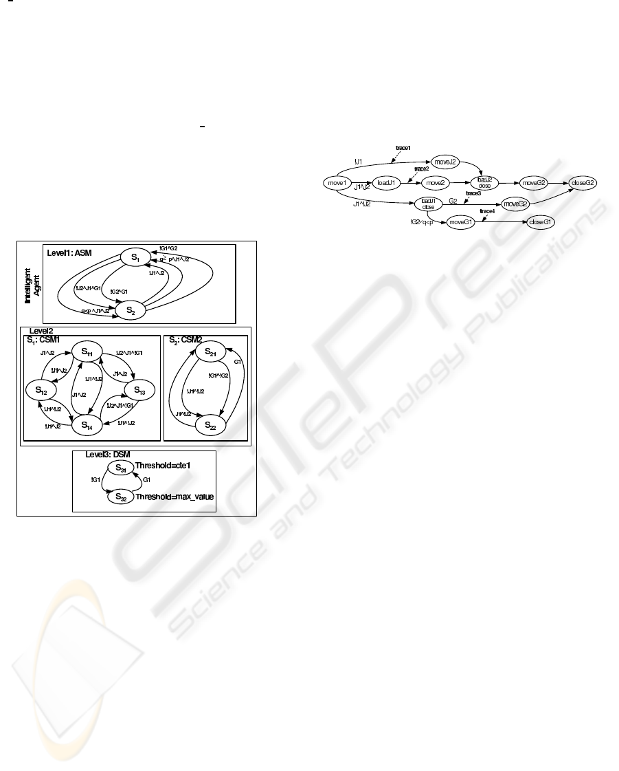
G1 CTL to remove pieces into Belt1. On the other
hand, we associate in the second level for the state S
1
the CSM CSM
1
defining the different reconfiguration
forms to apply when the first architecture is loaded in
the memory. In particular, when the state S
11
is active
and the Jack station J
1
is broken, then we activate the
state S
12
in which the Jac k station J
2
is alone run-
ning to place only one piece in the tin. In this case,
the internal behavior of the block Belt
CTL has to be
changed (e.g. the tin has to be transported directly to
the station J
2
). Finally, we specify in the data unit a
DSM where we change the value of Threshold if the
Gripper G
1
is broken (we suppose as an example that
we are not interested in the system performance when
the Gripper G
1
is broken).
Figure 2: Behavior of the reconfiguration agent.
6.2 System Behaviors
The different reconfiguration scenarios applied by the
agent define all the possible configurable behaviors
to follow by the system blocks when conditions are
satisfied. We specify in this paper these behaviors
with a unique System State Machine (denoted by
SSM) where each state corresponds to a particular
behavior of a block when a corresponding input event
occurs.
Running Example. In the EnAS system, we spec-
ify in Figure 3 the different system behaviors that
we can follow to resolve hardware problems or to
improve the system performance. In this example,
we distinguish 4 traces encoding 4 different behav-
iors. The trace trace1 implements the system behavior
when the Jack station J
1
is broken. The trace trace2
implements the system behavior to apply the second
production policy. The trace trace3 implemen ts the
system behavior when the Jack station J
2
is broken.
Finally the last scenario implements the system be-
havior when the Gripper G
2
is broken or when we
have to apply the first production policy. Note finally
that each state corresponds to a particular behavior
of a system block when the corresponding input event
occurs.
Figure 3: The system state machine: SSM.
6.3 Specification with Net
Condition/event Systems
To specify the synchronisation between the agent
and the system models, we apply the formalism
NCES which provides useful facilities allowing such
specification. We use in particular event/condition
signals from the agent to fix the behavioral trace to
follow in the SSM (e.g. a reconfiguration)and we use
event signals to synchronize the agent state machines:
ASM, CSM and DSM. Once the system is specified,
we apply the SESA model-checker available at our
laboratory to verify functional (like the attainability
of states or the deadlock) and temporal properties.
Running Example. We show in the Figure 4 the
agent and system models according to the NCES for-
malism. When the Jack station J
1
is broken, the agent
activates the place P
12
and sends a condition signal
to activate the trace trace1 in the system. Note that
the a rchitecture and control state machines are com-
municating by event signals to synchronize the agent
behavior. Finally, the state ”Well ” represents a dead-
lock in the system when the Jack stations J
1
and J
2
are
broken.
7 CONCLUSIONS AND FUTURE
WORKS
We propose in this paper a new reconfiguration se-
mantic of embedded systems and a classification of
all reconfigurationforms before we propose an agent-
based architecture to take into account all r easons as
RECONFIGURATION OF EMBEDDED SYSTEMS
161
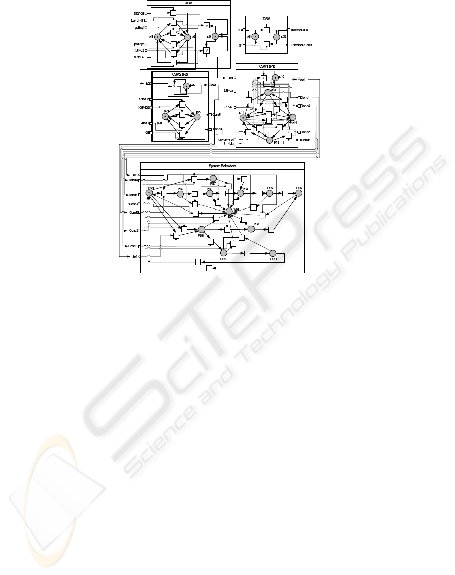
Figure 4: Design of the reconfigurable system with the NCES formalism.
well as reconfiguration forms. The agent applies au-
tomatic reconfigurations under fixed conditions, it is
specified with nested NCES to reduce the design com-
plexity and it is checked by the model checker SESA
to verify functional and temporal properties. In our
future works, we plan to propose an approach ana-
lyzing the schedulability of a system in the diff erent
reconfiguration scenarios in order to meet real-time
constraints.
REFERENCES
Al-Safi, Y. and Vyatkin, V. (2007). An ontology-based
reconfiguration agent for intelligent mechatronic sys-
tems. In Third International Conference on Industrial
Applications of Holonic and Multi-Agent Systems.
Angelov, C., Sierszecki, K., and Marian, N. (2005). De-
sign models for reusable and reconfigurable state ma-
chines. In L.T. Yang and All (Eds): EUC 2005, LNCS
3824, pp:152-163. International Federation for Infor-
mation Processing.
Khalgui, M. and Thramboulidis, K. (2008). An iec61499-
based development approach with focus on the de-
ployment of industrial control applications. In Ac-
cepted in International J ournal of Modelling, Identifi-
cation and Control.
Rausch, M. and Hanisch, H.-M. (1995). Net condition/event
systems with multiple condition outputs. In Sympo-
sium on Emerging Technolo gies and Factory Automa-
tion. Vol.1, pp.592-600.
Rooker, M. N., Sunder, C., Strasser, T., Zoitl, A., Hum-
mer, O., and Ebenhofer, G. (2007). Zero downtime re-
configuration of distributed automation systems : The
εcedac approach. In Third International Conference
on Industrial Applications of Holonic and Multi-Agent
Systems.
ICINCO 2008 - International Conference on Informatics in Control, Automation and Robotics
162
