
DEVELOPMENT OF AN ALTERNATIVE SYSTEM
FOR SUSPENDED GAIT ANALYSIS
Gustavo Freitas de Lima and Alberto Cliquet Jr.
Electrical Engineering Department, University of São Paulo, Av. Trabalhador São-carlense, 400, São Carlos-SP, Brazil
Department of Orthopedics, State University of Campinas, R. Tessalia Vieira de Camargo, 126, Campinas-SP, Brazil
Keywords: Functional Electrical Stimulation, suspended gait, ground reaction forces, knee joint angles, paraplegic,
rehabilitation, Spinal Cord Injury.
Abstract: Spinal Cord Injury (SCI) may impair an individual’s gait. For these cases, a rehabilitation technique that has
become more popular is Functional Electrical Stimulation (FES). Gait analysis is an important technique to
evaluate rehabilitation of patients undergoing FES-assisted therapy. This work proposes a system that
monitors gait variables – knee joint angles, and ground reaction forces (heel and metatarsal) – and uses them
as inputs for gait analysis of paraplegic patients. The methods for building the data acquisition hardware
(transducers and interface) and software are described, along with the transducer calibration methods. The
results show the final prototype for the gait analysis system, which allows comparison between different
individuals’ gaits, as well as different rehabilitation stages for the same individual. The software has a
recording feature, as well as digital control outputs, which may be used in the future for training an
Artificial Neural Network (ANN) and controlling the individual’s FES stimulator. In the near future, the
system may be of great applicability for suspended FES-assisted gait analysis and control.
1 INTRODUCTION
1.1 Human Gait
Gait may be defined as a form of biped progression
in which lower limb repetitive movements include
periods of double support – in which both feet are in
contact with the ground – followed by periods in
which only one foot supports the body (stance) and
the other is being moved above the ground (swing)
(Wall, 1999).
On a normal gait, the stance phase constitutes
60% of the gait cycle, and is defined as the interval
in which the reference foot is in contact with the
ground. The swing phase begins with heel contact
and ends when the foot leaves the ground (toe off
surface).
1.2 Gait Analysis
For individuals that suffer Spinal Cord Injury (SCI),
a technique that has contributed for rehabilitation is
Functional Electrical Stimulation (FES) (Castro and
Cliquet Jr., 2000). FES treatment may be associated
with dynamic suspension (Field-Fote, 2001). This
suspension allows a weight reduction, maintaining
the load on the lower limbs at a level they are able to
stand. It also stabilizes the trunk, resulting in better
balance for the patient, and lowers upper-limb
overload, frequently observed on walker-aided
training for paraplegic patients.
Gait analysis is an important tool for
biomechanical studies of the rehabilitation process.
Veltink, Liedtke, Droog, and van der Kooij (2005)
developed a gait analysis system using two
commercial six-degrees-of-freedom force and
moment sensors under a sandal. Giacomozzi and
Macellari (1997) constructed a compound
instrument by superimposing a dedicated pressure
platform on a commercial force platform.
The objective of this work is the development of
an alternative system for gait analysis, to be used on
the evaluation of patients’ rehabilitation for
suspended FES-assisted gait.
260
Freitas de Lima G. and Cliquet Jr. A. (2008).
DEVELOPMENT OF AN ALTERNATIVE SYSTEM FOR SUSPENDED GAIT ANALYSIS.
In Proceedings of the First International Conference on Biomedical Electronics and Devices, pages 260-263
DOI: 10.5220/0001049702600263
Copyright
c
SciTePress

2 METHODS
2.1 Determination of Variables
The first task was to determine which variables
would serve as inputs for the system. Various works
have been done proposing different models (Tong
and Granat, 1999; Pappas et al., 2004; Popovic et al.,
1998), each one showing advantages and
disadvantages. For this work, the idea was to be able
to measure the actual values for ground reaction
forces, and use them for comparison on gait
analysis, not as triggers for detection of foot contact.
Popovic et al. (1998) stated that ground reaction
forces alone could not be used for satisfactory gait
phase characterizing. In order to avoid this problem,
an extra variable was chosen to serve as system
input. The data posted on the CGA Normative Gait
Database (Kirtley, 2006) show kinematic and kinetic
analysis for healthy adults and children. Taking in
consideration the movement amplitude, easiness to
mount sensors, sensor stability during movement
and amount of signal noise, the variable selected was
knee flexion/extension.
2.2 Transducer Selection
Based on the studies conducted by Cunha (1999),
the chosen transducers for knee flexion/extension
angle determination were shape sensors. These
sensors use 0.25 mm diameter fiber optics, specially
treated to lose light by refraction proportionally to
the deflection suffered by the fibers. They present
some important characteristics, such as light weight
and a simple electronic signal processing package,
incorporated to the fiber optics.
For the ground reaction forces, the analysis was
based on the studies conducted by Leite (2003). The
author developed an instrumented crutch to measure
vertical reaction forces applied by patients during
gait, using strain gages.
Strain gages are resistors composed of a very
thin conductive layer over an isolating compound.
The sensor is glued on a structure, and when there is
some deformation caused by applied forces on the
structure, it is possible to determine the value of the
force, since it depends only on the type of material
and the geometry of the structure.
The fact that strain gages require a rigid structure
to operate represents a disadvantage for this kind of
sensors. The solution found for the problem was to
construct cylindrical aluminum rings to work as load
cells for the strain gages. For each load cell, a metal
base and a semi-spherical top were constructed, so
that the top’s radius helps bring the applied loads as
close as possible to vertical. Figure 1 shows one of
the load cells with the strain gages attached (left)
and with the protective covering, metal base and top
(right).
Figure 1: Ground reaction force sensors (load cells).
Three load cells were made for each foot, and
they were attached to a sandal, mounted on
cylindrical metal plates. One load cell was
positioned in the heel area, and the other two were
positioned in the metatarsal area, connected in
parallel – in order to compensate different styles of
stepping patterns.
2.3 Hardware Interface
The hardware interface circuit consists of anti-alias
filters (cutoff frequency of 18 Hz), voltage
regulators (± 5VDC), and amplifiers with adjustable
gains for the strain gages. The information was
acquired using a data acquisition board.
The circuit is enclosed in a box, connected to the
data acquisition board, and also to a smaller
interface box, which is positioned around the
patient’s waist, and has connection hubs for the
instrumented sandals and shape sensors. The
transducers connected to the patient’s interface box
are shown in Figure 2.
Figure 2: Transducers and patient’s interface.
2.4 Transducer Calibration
To calibrate the shape sensors, they were attached to
two articulated flat metal bars, and a protractor. The
voltage values corresponding to each 5º angle
interval, from -140º to 140º, were collected.
DEVELOPMENT OF AN ALTERNATIVE SYSTEM FOR SUSPENDED GAIT ANALYSIS
261
For the load cells, the calibration was performed
using a dynamometer, and the voltage values for
each 50 N interval, from 0 to 1000 N were collected.
For both cases, the results showed a linear behavior.
2.5 Software Interface
The software used to program the system was
LabVIEW 6.1. It has some advantages, including
user-friendly graphic interface, and compatibility
with the data acquisition board.
The interface software has a monitoring module,
which allows visually following the behavior of
knee flexion/extension angles, and ground reaction
forces – heel and metatarsal. It is also possible to
record them in a spreadsheet file for data analysis.
The visual interface shows three screens (selectable
using tabs): the “Main” screen, which has all the
controls and configuration options; the “Angles”
screen, which shows the graphics for the knee
flexion/extension angles, and the “Forces” screen,
which shows the graphics for the ground reaction
forces. Figure 3 illustrates the “Forces” screen.
Figure 3: Graphical interface for force measurements.
On the main screen, there is a calibration
function. This function should be used when the
patient already has the sandals on, but has not stood
up yet. The function performs 200 force acquisitions
for each load cell, and then calculates the average of
these forces. The result is then used as linear
coefficients for the calibration curves of the force
transducers. This way, the value shown with the
patient sitting is zero, despite the applied force for
tightening the sandals.
3 RESULTS
The final prototype was mounted on a healthy
individual and tested, to check its functionality. The
individual’s characteristics are: male, 25 years old,
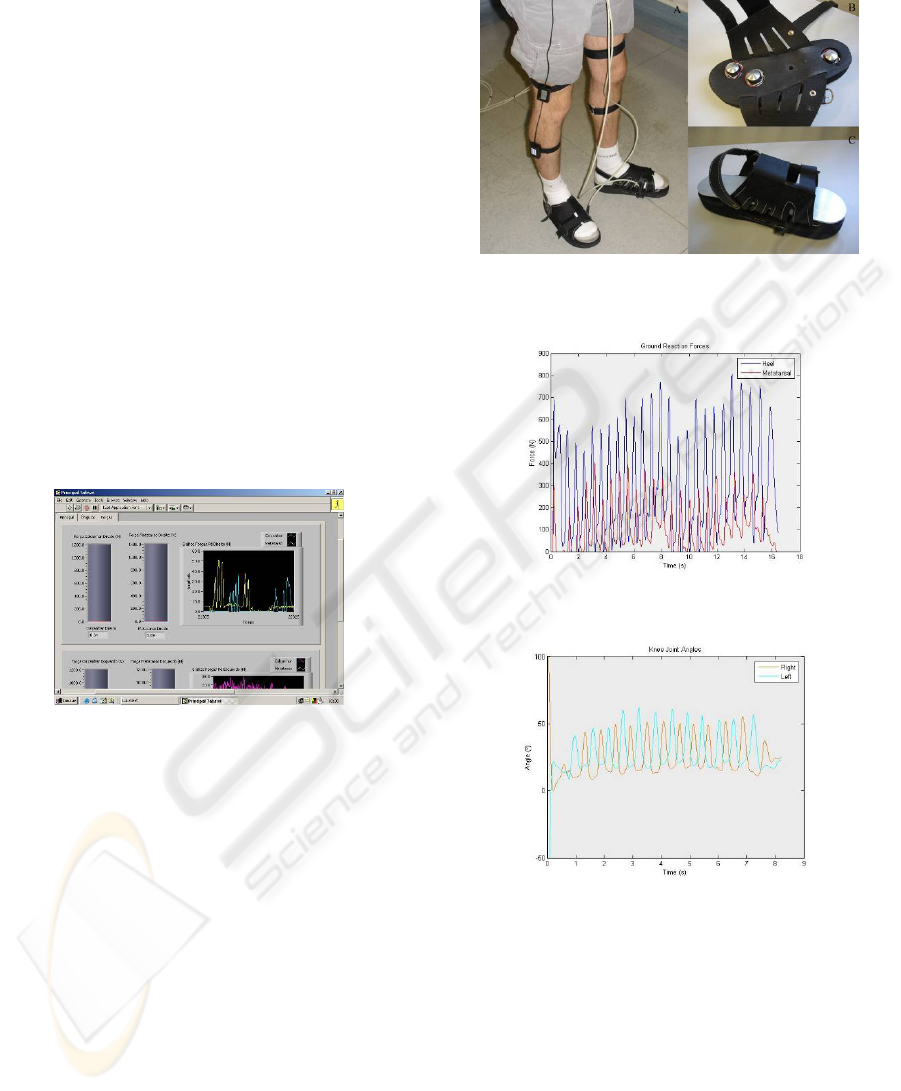
height of 1.81m, weight of 69.0kg. Figure 4 shows
the subject wearing the instrumented sandals and the
shape sensors.
Figure 4: (A) System mounted on healthy individual; (B)
Detail of sensor positioning in the sandal; (C)
Instrumented sandal.
Figure 5: Ground reaction forces on right foot for healthy
individual.
Figure 6: Knee joint angles for healthy individual.
The individual was asked to walk normally in a
straight line for about 15m while the values of
ground reaction forces and knee joint angles were
recorded. Figures 5 and 6 show the resulting values
for the ground reaction forces on the left foot, and
the knee joint angles, respectively.
For the angle values, the convention adopted was
zero for straight vertical position, positive angles for
knee flexion and negative angles for knee extension.
BIODEVICES 2008 - International Conference on Biomedical Electronics and Devices
262

4 DISCUSSION
The ground reaction forces observed in Figure 5
show peaks of about 780N on the heel, which
correspond to 113% of the individual’s weight. On
the metatarsal area, the peak force values are around
380N (55% of the individual’s weight). This may be
due to the softness of the sandal sole, which may
still absorb part of the applied forces. It’s possible to
distinguish the gait phases of initial contact (heel
force peak), mid stance (heel and metatarsal force
intersection), and terminal stance (metatarsal force
peak).
The knee joint angles observed in Figure 5
follow the pattern presented on the CGA Normative
Gait Database (Kirtley, 2006). The waveforms
present a repetitive pattern, confirming that the
shape sensors did not move during the acquisitions.
5 CONCLUSIONS
The values of ground reaction forces and knee joint
angles may be observed during the gait, and the
recorded values may be used for further analysis,
comparing different styles of gait, or different
rehabilitation stages for the same individual.
This system may be used as an alternative to the
force platforms. The disadvantages are that it
requires some time for donning, and it can only
measure vertical forces. But it presents some
advantages, such as: the subject may walk freely
(within the limitation of the cables), and does not
have to step exactly on the load cell, resulting in a
more natural gait; also, the system allows
monitoring two critical force points for each foot,
and not just the resulting force.
Considering the aforementioned advantages, an
important possible application for this alternative
system is suspended FES-assisted gait. In this case,
therapists may follow the recovery of patients
undergoing this kind of treatment by analyzing the
gait on different stages of the rehabilitation process.
In the future, the recordings of gait sessions may be
used as inputs for a closed-loop FES control. The
system already has two digital inputs and two
outputs, which may be used to trigger an electrical
stimulator. Since the software is open, an Artificial
Neural Network (ANN) may be programmed to
control the FES during gait, using the patient’s own
recorded data for training. With this implementation,
the patient will not need to trigger the stimulation
manually, and may direct all the attention to the
walking activity.
ACKNOWLEDGEMENTS
The authors would like to acknowledge the support
of the State of São Paulo Foundation for Research –
FAPESP and the Coordination for the Improvement
of High Education Personnel – CAPES – Ministry of
Education, Brazil.
REFERENCES
Castro, M, C. F.; Cliquet Jr., A. An artificial grasping
system for the paralysed hand. Artificial Organs.
2000;24:185-188.
CGA Normative Gait Database. Produced by Chris
Kirtley. [cited 2007 Jul 10]. Available from:
<http://www.univie.ac.at/cga/data/index.html>.
Cunha, F. L. Obtenção e uso dos acoplamentos
cinemáticos interfalangianos e interdigitais no projeto
de próteses antropomórficas para membros
superiores. Vitória: UFES; 1999.
Field-Fote, E. C. Combined use of body weight support,
functional eletric stimulation, and treadmill training to
improve walking ability in individuals with chronic
incomplete spinal cord injury. Arch Phys Med Rehabil.
2001;82: 818-824.
Giacomozzi, C.; Macellari, V. Piezo-Dynamometric
Platform for a More Complete Analysis of Foot-to-
Floor Interaction. IEEE Transactions on
Rehabilitation Engineering. 1997;5: 322-330.
Leite, F. I. L. Desenvolvimento de uma muleta
instrumentalizada para fins de acompanhamento
clínico. São Carlos: EESC-USP; 2003.
Pappas, I.; Keller, T.; Mangold, S.; Popovic, M. R.; Dietz,
V.; Morani, M. A reliable gyroscope-based gait-phase
detection sensor embedded in a shoe insole. IEEE
Sensors. 2004;4:268-274.
Popovic, M. R.; Keller, T.; Ibrahim, S.; Von Büren, G.;
Morani, M. Gait identification and recognition sensor.
International Workshop on Functional Electrical
Stimulation; 1998; Vienna, Austria; 1998. p. 153-156.
Tong, H.; Granat, M. H. A practical gait analysis system
using gyroscopes. Medical Engineering & Physics.
1999;21:87-94.
Veltink, P. H.; Liedtke, C.; Droog, E.; van der Kooij, H.
Ambulatory Measurement of Ground Reaction Forces.
IEEE Transactions on Neural Systems and
Rehabilitation Engineering. 2005;13:423-427.
Wall, J. C. The Gait. In: Durward, B. R.; Baer, G. D.;
Rowe, P.J., editors. Functional human movement:
measurement and analysis. Oxford: Butterworth
Heinemann; 1999. p. 93-105.
DEVELOPMENT OF AN ALTERNATIVE SYSTEM FOR SUSPENDED GAIT ANALYSIS
263
