
WIRELESS POSITION LOCATION SYSTEM FOR INDOOR
ENVIRONMENTS
Matthew D’Souza
School of Information Technology and Electrical Engineering, The University of Queensland, Brisbane, Australia
Adam Postula
National ICT Australia – Queensland Laboratory, Brisbane, Australia
Montserrat Ros
School of Electrical, Computer and Telecommunications Engineering, University of Wollongong, Wollongong, Australia
Keywords: Wireless Sensor Network, Location System, Zigbee, Emergency Situations.
Abstract: Location systems are used for a variety of navigation applications. Current Location systems are designed to
provide accurate distance position coordinates. There are tracking or logistic applications where actual
position coordinates are not necessary. Determining the room in a building an object is located can be more
useful then the actual coordinates. We present an inexpensive and robust wireless location beacon network
that can track the location of emergency responders or users in an indoor environment. Location beacons are
placed at predetermined positions in a building. The location beacons are used to determine the presence of
the user in an area of a building. The location beacon network does not track the user's coordinates. The
location beacon network uses the ZigBee/802.15.4 wireless communications protocol. Our paper examines
the use of the Zigbee protocol to determine a user’s location. Two realtime location tracking mechanisms
are also analysed and tested. A successful prototype of the location beacon network was created and tested.
1 INTRODUCTION
In recent years, position locating systems such as
Global Positioning (GPS) have achieved widespread
use for a variety of navigation applications.
Conventional location systems are designed to
provide accurate distance position coordinates. Such
systems often require sophisticated and expensive
electronic tracking devices and an extensive
infrastructure. An example is the network of
satellites used by GPS systems or the cellular towers
used by the GSM communications network (Otsason
et al., 2005). There are tracking or logistic
applications where actual position coordinates are
not necessary. Determining the room in a building
an object is located may be more useful then the
object’s exact coordinates. If accurate position
coordinates are not required by the application then
less sophisticated tracking devices and infrastructure
can be used.
This paper presents a relatively inexpensive and
robust wireless location beacon network that tracks
the location of users in an indoor environment. The
location beacon network is designed for use with
emergency responders; operating inside a building.
The location beacon network also allows a user to
determine their location. Location beacons are
placed at known positions throughout a building.
The location beacons are only used to determine the
presence of the user within a particular region of a
building. An example is that a location beacon is
placed within a room, any users that enter that room
will be detected and their current position will be
identified as that room. The location beacon network
does not track actual coordinates of users.
The location beacon network infrastructure uses
the ZigBee/802.15.4 wireless communications
protocol. Zigbee is a low data rate wireless network
communications protocol that is designed to operate
on devices with limited computing resources and
109
D’Souza M., Postula A. and Ros M. (2007).
WIRELESS POSITION LOCATION SYSTEM FOR INDOOR ENVIRONMENTS.
In Proceedings of the Second International Conference on Wireless Information Networks and Systems, pages 109-116
DOI: 10.5220/0002147901090116
Copyright
c
SciTePress
cater for large networks of active devices (ZigBee
Alliance, 2006). This paper explores the use of the
Zigbee protocol to determine a user’s location and
analyses two realtime location tracking mechanisms.
Issues relating to the deployment and the integration
of the location beacon network with conventional
local area networks are also discussed.
This paper is organized into 7 sections. Section 2
presents a review of related work. Section 3
describes a typical scenario. Sections 4 discuss the
location beacon network implementation. Section 5
presents the findings of testing conducted of the
location beacon network. Section 6 provides an
analysis of the location beacon network and
discusses deployment issues. Conclusions and futher
areas of investigation are discussed in Section 7.
2 RELATED WORK
There are different types of wireless technologies,
other than GPS, that have been investigated for
location systems. Unfortunately, GPS is not suitable
for indoor use and this has led to research into the
use of other wireless technologies including UWB
(Schwarz et al., 2005), ultrasonic and GSM (Otsason
et al., 2005) platforms. Regulations are not clear for
the use of UWB, and ultrasonic location detection
still require the use of RF transceivers. GSM uses
existing infrastructure, however accurate position
resolution indoors is difficult.
Lamarca et al (Hightower et al., 2006, LaMarca
et al., 2005) describe the Placelab geophysical
location system that allows users to determine their
position in an urban environment. Placelab uses the
received signal strength indicators (RSSI) of Wifi
hotspots and GSM broadcast towers to determine a
user's position. The Placelab software uses a
database of known Wifi hotspots and GSM
broadcast towers. The Placelab software can be used
with a PDA or laptop with Wifi or GSM
connectivity. Localisation accuracy is stated as being
less then GPS, with 20-25m using Wifi hotspots and
100 to 150m for GSM broadcast towers. A similar
technique of using RSSI is employed by the location
beacon network.
A classical case of using wireless beacons for
navigation is presented in (Want et al., 1992). The
active badge project achieved a 5-10m accuracy
using infrared. The main drawback of this platform
is that it required line of sight between beacons.
An extension of the Active Badge Project was
the ORL location system by (Ward et al., 1997)
which developed a prototype network of ultrasonic
beacons to perform realtime tracking of tagged
mobile devices in an office environment. Other
ultrasonic location systems such as the Cricket Mote
(Priyantha et al., 2000) and the system by
(McCarthy et al., 2006) describes how a network of
ultrasonic beacons using time of flight analysis can
determine distance position locations.
2.1 Zigbee Protocol
The Zigbee protocol is a wireless communications
network protocol that is designed for low powered,
Figure 1: Location Beacon Network.
WINSYS 2007 - International Conference on Wireless Information Networks and Systems
110
low processing platforms (Baker, 2005). Its
supported features are Mesh Networking, a unique
64-bit address, Low Data Rates 20kbps – 250kbps
and simple application profiles. Zigbee is
specifically aimed at aimed for ‘cable replacement’
applications. It operates in the unlicensed ISM
2.4GHz frequency band. Current Zigbee protocol
radio chipsets have a large indoor range which can
be up to 100m. The Zigbee protocol stack is divided
into two sections, Zigbee and 802.15.4. The lower
PHY and MAC layers are defined by the IEEE
802.15.4 protocol and the upper layers are defined as
Zigbee protocol (ZigBee Alliance, 2006).
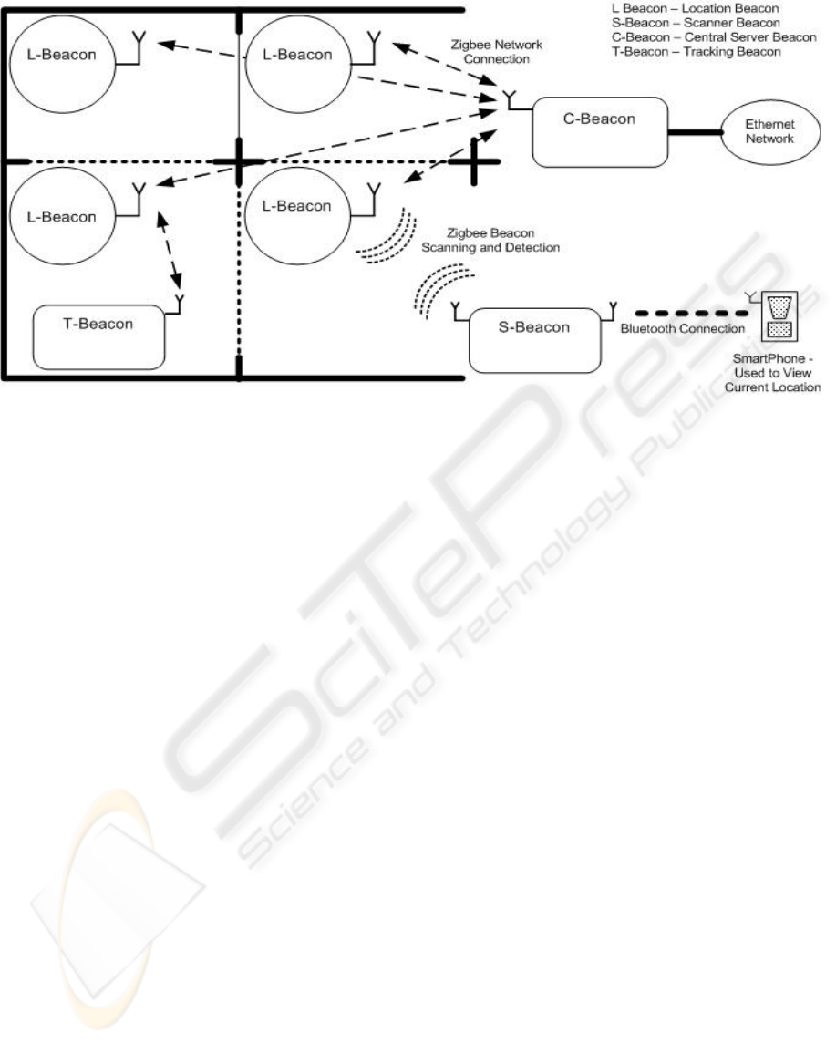
3 USER SCENARIO
The location beacon network was designed to track
the position of users, in this case emergency
response personnel, within a building. Figure 1
shows an example deployment of the location
beacon network. Location beacons are placed at
known positions throughout a building.
A user carries either a scanner or tracker beacon
to have their current position tracked by the central
beacon. The scanner beacon allows the user to view
their location as shown in Figure 3. The tracker
beacon does not allow the user to view their current
position. The tracker beacon is activated by the user
when required.
4 LOCATION BEACON
NETWORK
The network as see in Figure 1 consists of four
different beacons, central, location, scanner and
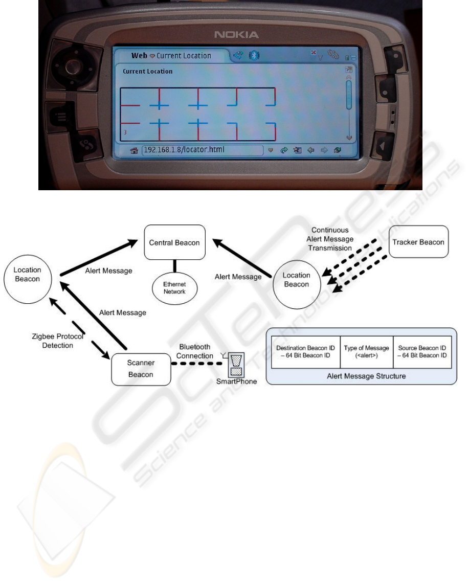
Figure 3: Scanner Beacon Locator Webpage Showing Current Location.
Figure 3: Location Beacon Network Message Passing Hierarchy.
WIRELESS POSITION LOCATION SYSTEM FOR INDOOR ENVIRONMENTS
111

tracker beacons. Scanner and tracker beacons are
carried by users to determine their current location.
The location beacons are used to determine a
scanner or tracker beacon’s position. The central
beacon displays the current position of the scanner
and tracker beacons. The location beacon network is
not designed to track users with respect to distance
coordinates but rather to determine their position
within in a particular room or section of a building.
4.1 Operation
The location beacon network uses the Zigbee
protocol to provide communication links between
the different beacons. Alert messages are used by the
scanner and tracker beacons to report their current
position to the central node.
Figure 3 shows the
communication message passing hierarchy between
the different beacons and the structure of the alert
message.
4.2 Central Beacon
Each location beacon is within wireless
communications range of a central beacon. The
central beacon is connected to a standard Ethernet
work and is used to track the current position of the
user (with scanner or tracker beacon) within the
location beacon network. The central beacon is
accessed via a webpage interface. It displays the
current locations of users.
4.2.1 User Interface
As shown in Figure 4, the user interface consists of a
webpage that is dynamically updated to display the
current locations of users. The webpage relies on
CGI scripting and an SQL database to track the last
location of the user. The SQL tracking database
records the details from each beacon.
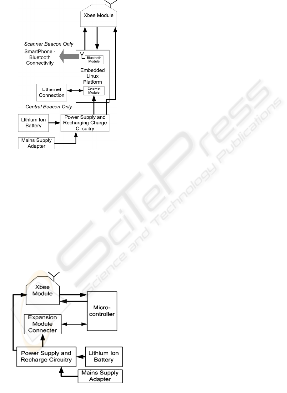
4.2.2 Implementation
The central beacon was implemented using an
embedded Linux module connected to an XBee
Zigbee/802.15.4 module (MaxStream, 2006). The
central beacon is connected to the standard mains
power supply and also has a rechargeable Lithium
Ion battery. The battery serves as a backup power
supply during a mains power outage. The central
beacon has Ethernet connectivity. The architecture
of the central beacon can be seen in Figure 4.
4.3 Location Beacon
Each location beacon is in range of a central
beacon.The position of each location beacon is
known by the central and scanner beacons. The
location beacons are detected by the scanner beacon.
The minimum distance between the location beacons
is 6m. This is required to allow the scanner beacon
to use the received signal strength indicator for
determining its nearest location beacon. More details
are given in section 6.
4.3.1 Implementation
The location beacon was designed to be simplistic in
functionality, to reduce hardware and software costs.
The architecture of the location beacon can be seen
in Figure 5. The location beacon uses an xBee
Zigbee/802.15.4 wireless transceiver module from
MaxStream. Each xBee module has a unique 64-bit
network address (MaxStream, 2006). This network
address is used as the location beacon’s identifier.
The location beacon can be connected expansion
modules. Such modules consist of sensor platforms,
i.e. climatic sensors such as temperature or
humidity. The location beacons are plugged into
mains power. Each beacon has a Lithium Ion battery
to function as a power source if mains power is
disrupted. The beacon was found to operate for 9
hours when powered solely from the battery.
4.4 Scanner Beacon
The scanner beacon is carried by a user to determine
their location. The scanner beacon detects location
beacons in near proximity in order to determine a
current user’s position. The scanner beacon detects
location beacons within a 10m range. The detected
location beacon’s ID and Received Strength Signal
Indicator (RSSI) are stored in an SQL database. The
RSSI is a measurement of the power of the received
radio signal by the xBee transceiver module.
The nearest beacon is determined by the largest
RSSI value detected. Once the nearest location
beacon has been determined, the scanner beacon
connects to it and transmits an alert message to it.
The receiving location beacon then retransmits the
alert message to the central beacon.
WINSYS 2007 - International Conference on Wireless Information Networks and Systems
112
4.4.1 User Interface
A smartphone can be used to view the current
position determined by the scanner beacon. The
smartphone connects via a network point to point
protocol (PPP) link via a Bluetooth connection to the
scanner beacon carried by the user. The smartphone
used was a Nokia 7710. As shown in
Figure 3, the
user interface consists of a webpage that is
dynamically updated to display the current location
of the user. The webpage relies on CGI scripting and
an SQL database to display the current location. The
SQL database records the details from each beacon.
4.4.2 Implementation
The scanner beacon has a similar hardware
implementation to the central beacon except that it
supports Bluetooth but not Ethernet connectivity.
The architecture of the scanner beacon can be seen
in
Figure 4.
4.5 Tracker Beacon
The tracker beacon allows the user’s position to be
determined by the location beacon network. It does
not allow the user to view their current position. The
tracker beacon is activated by the user when
required. The tracker beacon has the same hardware
implementation as the location beacon.
As shown in
Figure 3, the tracker beacon
continuously transmits an alert message. The
Tracker beacon is designed to have a short
transmission range of 1 to 3m. The minimum
separation distance between location beacons is 6m.
The received signal strength indicator is not required
to determine the location of the tracker beacon, as
required by the scanner beacon.
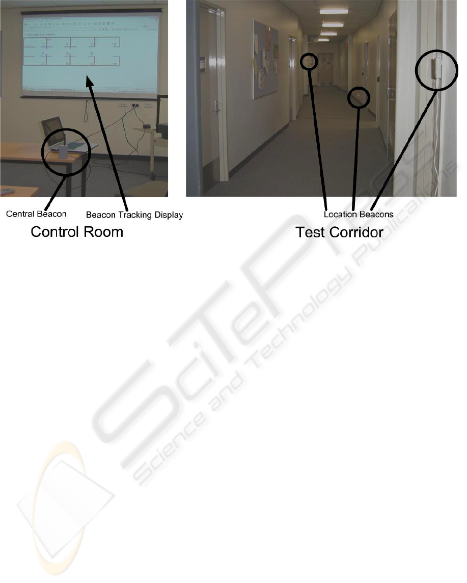
5 TESTING
The test setup of the beacon network consisted of six
location beacons, one scanner, one tracker and one
central beacon. Figure 6 shows the location beacons
placed 5m apart, in a corridor and adjacent rooms.
The test area was approximately 35m
2
.
Office walls were found to act as barriers for the
Zigbee/802.15.4 transceiver signals. This was
advantageous, when placing a single location beacon
within a room, as this allowed the scanner determine
its nearest location beacon as being in that particular
room. This because the received signal strength
levels is higher for location beacon in sight of the
scanner compared to a location beacon that is closer
in distance but is instead situated in an adjacent
room. The location beacon was found to be able to
communicate with the central beacon through office
walls. The central beacon uses a quarter-wave
antenna that is sensitive to receive transmissions
from the location beacons.
Figure 5: Location Beacon Hardware Architecture.
Figure 4: Central Beacon Hardware Architecture.
WIRELESS POSITION LOCATION SYSTEM FOR INDOOR ENVIRONMENTS
113
6 ANALYSIS
This section analyses the location beacon network
system. The use of the Zigbee protocol and network
interoperability is discussed. Issues relating to
deployment and the location determining
mechanisms used are also discussed.
6.1 Zigbee Protocol
The main advantage of using the Zigbee protocol is
that it is designed primarily to provide robust and
reliable wireless communications for networks
containing large numbers of simple computing and
battery powered devices. The location beacon
network is designed to operate in during a mains
power outage and hence the location beacons can
operate from a rechargeable battery source.
The Zigbee lower protocol stack 802.15.4
defined PHY layer allows the location beacons to
connect and disconnect quickly. Connection times
are 30ms compared to 20s for Bluetooth (Baker,
2005). The use of received signal strength indicator
(RSSI) allowed the Zigbee protocol to be adapted
for use in the location beacon network. The RSSI
measurement allows the location beacon network to
proximate the location of scanner/tracker beacons
within a known region but not actual distance
coordinates.
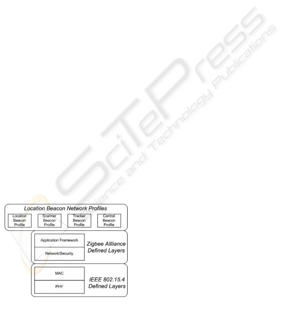
Other advantages include the 64-bit ID addresses.
This allows the beacon network to handle a large
number of active beacons. The Zigbee
communications protocol stack provides an
application framework layer that allows
customizable application profiles to be easily
integrated with the Zigbee stack. As seen in Figure
7, each type of beacon has a unique application
profile that interacts with the Zigbee/802.15.4
protocol stack. Each application profile is
implemented on the embedded processor or
microcontroller platform used for each beacon.
6.2 Location Determining
Location Determining was performed in this system
using the received signal strength indicator. In this
paper RSSI and transmission power levels were the
main factor in calculating locations. Power control
and detection features are supported by the
Zigbee/802.15.4 wireless transceiver devices used.
Two types of RSSI location tracking mechanisms
were tested. The first mechanism involved actively
scanning and detecting the RSSI levels for location
beacons in near proximity. This mechanism was
tested by the scanner beacon. The advantage of
using this method is that the scanner can employ
various techniques to determine the nearest location
Figure 6: Test Setup of Location Beacon Network.
WINSYS 2007 - International Conference on Wireless Information Networks and Systems
114
beacon. One disadvantage discovered with this
approach is that scanning time period is required in
order to scan for beacons in proximity.
The scanning time period was approximately 100ms.
This increased the time it takes to detect and issue an
alert message to the central beacon. The average
maximum response time was measured to be ~3s.
The minimum response time estimated to be 500ms.
The second form of location determining
mechanism tested, involved the continuous
transmission of alert messages, over a short distance.
This was tested by the tracker beacon. The tracker
beacon’s transmission power was limited to ensure
that the only location beacons within a 2m to 3m
radius could successfully receive the alert message.
The advantage of this mechanism is that less time is
taken for the central beacon to be aware of the
tracker beacon’s position.
6.3 Network Interoperability
The location beacon network was designed to be
interoperable with standard local area networks. The
central beacons were developed on embedded Linux
platforms. The use of Linux in this situation was
advantageous because it provided common network
interface mechanisms such as sockets and SQL
database functions. The central beacon’s tracking
database is accessible via a web interface.
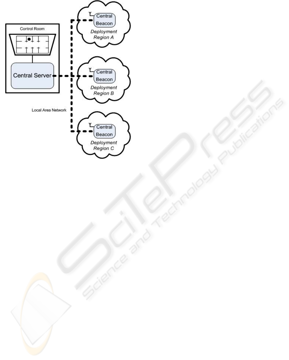
6.4 Deployment
In order to deploy the location beacon network
within a building, several central beacons and
location beacons are used. Currently without the use
of Zigbee mesh networking, the central beacons
currently have to be within range of all location
beacons. The central beacons are currently limited in
range to an average of radius of 20m inside a typical
building.
To overcome range limitations, a building is
divided into regions. A region is a section of floor
level. A central beacon and location beacons would
deployed within a region. Central beacons would be
connected via an Ethernet network to a server as
shown in Figure 8. Each central beacon’s tracking
database can be accessed and integrated into the
server’s building tracking database. This allows the
monitoring of scanner and tracker beacons
throughout the building.
7 CONCLUSION AND FURTHER
WORK
In this paper we presented a location beacon
network system that tracks users in an indoor
environment. The location beacon network consisted
of location beacons placed at known positions
throughout a building. Users carry scanner and
tracker beacons to allow their current position to be
monitored by a control centre. The location beacon
network was designed to operate during a power
outage and hence the location beacons can operate
from a rechargeable battery source.
The requirement of the location beacon network
system was to determine the position of a
scanner/tracker beacon within in a region and not an
exact distance position. The location beacon network
used the Received Signal Strength Indicator (RSSI)
as a means of determining the proximity of a
scanner/tracker beacon to a location beacon. This
paper analysed the use of the Zigbee protocol and
RSSI as a location determining mechanism and
found that the Zigbee communications protocol
provided useful advantages compared to other
protocols. Two mechanisms: scanning and tracking
that used RSSI as a proximity detector were
analysed. Both mechanisms have advantages but it
was found that the tracker mechanism had a faster
tracking time.
The location beacon network can be integrated
with standard local area networks to allow
deployment over a much wider area. The location
beacon network was successfully tested over an area
of approximately 35m
2
.
All though a successful prototype of the location
beacon network was created and tested, there are
further issues of investigation. Such issues include
larger scale area deployments and long term
reliability.
Figure 7: Zigbee/802.15.4 Communications Protocol Stac
k
used for Location Beacon Network.
WIRELESS POSITION LOCATION SYSTEM FOR INDOOR ENVIRONMENTS
115
The future addition of WLAN connectivity and the
use of high antennas to the central beacons will
allow the central beacons to be more easily deployed
and cover a wider area.
ACKNOWLEDGEMENTS
The authors acknowledge the financial support of
National ICT Australia (NICTA). NICTA is funded
by the Australian Governments Backing Australia’s
Ability initiative, in part through the Australian
Research Council.
REFERENCES
Baker, N. (2005) ZigBee and Bluetooth strengths and
weaknesses for industrial applications. Computing &
Control Engineering Journal, 16, 20-25.
Hightower, J., LaMarca, A. & Smith, I. E. (2006) Practical
Lessons from Place Lab. Pervasive Computing, IEEE,
5, 32-39.
LaMarca, A., Chawathe, Y., Consolvo, S., Hightower, J.,
Smith, I., Scott, J., Sohn, T., Howard, J., Hughes, J.,
Potter, F., Tabert, J., Powledge, P., Borriello, G. &
Schilit, B. (2005) Place Lab: device positioning using
radio beacons in the wild. Pervasive Computing. Third
International Conference, PERVASIVE 2005.
Proceedings (Lecture Notes in Computer Science Vol.
3468). Springer-Verlag. 2005, 116-33.
MaxStream (2006) XBee ZigBee OEM RF Module,
http://www.maxstream.net/products/xbee/xbee-oem-
rf-module-zigbee.php.
McCarthy, M., Duff, P., Muller, H. L. & Randell, C.
(2006) Accessible Ultrasonic Positioning. Pervasive
Computing, IEEE, 5, 86-93.
Otsason, V., Varshavsky, A., LaMarca, A. & de Lara, E.
(2005) Accurate GSM indoor localization. UbiComp
2005: Ubiquitous Computing 7th International
Conference, UbiComp 2005. Proceedings (Lecture
Notes in Computer Science Vol. 3660) . Springer-
Verlag. 2005, 141-58.
Priyantha, N. B., Chakraborty, A. & Balakrishnan, H.
(2000) The Cricket location-support system. MobiCom
2000. Proceedings of the Sixth Annual International
Conference on Mobile Computing and Networking.
ACM. 2000, 32-43.
Schwarz, V., Huber, A. & Tuchler, M. (2005) Accuracy of
a commercial UWB 3D location/tracking system and
its impact on LT application scenarios.
Want, R., Hopper, A., Falcao, V. & Gibbons, J. (1992)
The active badge location system. ACM Transactions
on Information Systems, 10, 91-102.
Ward, A., Jones, A. & Hopper, A. (1997) A new location
technique for the active office. Personal
Communications, IEEE [see also IEEE Wireless
Communications], 4, 42-47.
ZigBee Alliance (2006) ZigBee Specification,
http://www.zigbee.org/en/spec_download/.
Figure 8: Location Beacon Network Large Scale
Deployment.
WINSYS 2007 - International Conference on Wireless Information Networks and Systems
116
