
IMPEDANCE MATCHING CONTROLLER FOR AN INDUCTIVELY
COUPLED PLASMA CHAMBER
L-type Matching Network Automatic Controller
Giorgio Bacelli, John V. Ringwood and Petar Iordanov
Department of Electronic Engineering, National University of Ireland, Maynooth, Ireland
Keywords:
Automatic Impedance Matching, Matching Network, Impedance Sensor, Inductively Coupled Plasma.
Abstract:
Plasma processing is used in a variety of industrial systems, including semiconductor manufacture (deposition
and etching) and accurate control of the impedance matching network is vital if repeatable quality is to be
achieved at the manufacturing process output. Typically, impedance matching networks employ series (tune)
and parallel (load) capacitors to drive the reflection coefficient on the load side of the network to zero. The
reflection coefficient is normally represented by real and imaginary parts, giving two variables to be controlled
using the load and tune capacitors. The resulting problem is therefore a nonlinear, multivariable control prob-
lem. Current industrial impedance matching units employ simple single-loop proportional controllers, which
take no account of interaction between individual channels and, in many cases, may fail to tune altogether, if
the starting point is far away from the matching point. A hierarchical feedback controller is developed which,
at the upper level, performs a single-loop tuning, but with the important addition of a variable sign feedback
gain. When convergence to a region in the neighbourhood of the matching point is achieved, a dual single-loop
controller takes over, which gives fine tuning of the matching network.
1 INTRODUCTION
The BAsic Radio frequency Inductive System
(BARIS) is an experimental inductively coupled
plasma chamber used to study the closed-loop con-
trol of plasma states. Inductively coupled plasma is
ignited by an electromagnetic field irradiated from
an antenna connected to a Radio Frequency (RF)
power supply. An Impedance Matching Unit (IMU)
is used to match the impedance of the antenna to the
impedance of the generator, in order to deliver the
maximum power to the plasma. The IMU is com-
posed of a matching network, a Phase and Magni-
tude Detector (PMD) and a controller that automat-
ically tunes the matching network using the informa-
tion supplied by the PMD. Each time plasma param-
eters or plasma state set-points are changed (i.e. RF
power, pressure, gas mixture), the plasma impedance
also changes. In addition, when the controller is tun-
ing the matching network, the reflection coefficient
is decreasing, therefore the power delivered to the
plasma is increasing causing a variation of the plasma
states and, as a consequence, a variation of plasma
impedance. The main issue regarding the existing
driver circuitry associated with the original controller
is the global convergence (Mazza, 1970), that is, if the
initial conditions of the system are far away from the
matching point, the controller may not be able to tune
the matching network.
The automatic impedance matching problem has been
solved using neural networks (Vai and Prasad, 1993),
genetic algorithms (Thompson and Fidler, 2000) (Sun
and J.K., 1997) (Sun and J.K., 1999), deterministic
tuning algorithms with look-up tables (Moritz and
Sun, 2001) and using adaptive systems (Parro and
Pait, 2003) (Ida et al., 2004c) (Ida et al., 2004a)
(De Mingo et al., 2004) (Ida et al., 2004b); nonlinear
control systems have been also considered (Cottee,
2003). In all of the above mentioned cases, the load
impedance is not affected by the matching conditions
while, in the case studied (inductively coupled plasma
discharges), the load impedance is varying during the
matching process. In this paper a hierarchal struc-
ture controller has been designed; it is composed of
202
Bacelli G., V. Ringwood J. and Iordanov P. (2007).
IMPEDANCE MATCHING CONTROLLER FOR AN INDUCTIVELY COUPLED PLASMA CHAMBER - L-type Matching Network Automatic Controller.
In Proceedings of the Fourth International Conference on Informatics in Control, Automation and Robotics, pages 202-207
DOI: 10.5220/0001648802020207
Copyright
c
SciTePress
a higher level coarse controller that drives the sys-
tem close to the matching point, and lower level feed-
back controller for the fine tuning. An impedance
sensor has been also designed to supply more reliable
measurements of the reflection coefficient to the con-
troller.
2 BARIS IMPEDANCE
MATCHING
The BARIS is an experimental plasma chamber, used
to study plasma phenomenon for applications in semi-
conductor manufacturing, and generates an argon and
oxygen plasma that is ignited by a 13.56MHz mag-
netic field irradiated from an antenna. The main parts
that compose this device are the plasma discharge
chamber, the RF power supply, the matching unit and
the real time monitoring and control of the system.
Match
network
Plasma
Antenna
Ar O2
Vacuum
pump
Gate
valve
Discharge chamber
PMD
RF
power
supply
Mass flow
controllers
Impedance
matching
controller
Figure 1: BARIS block diagram.
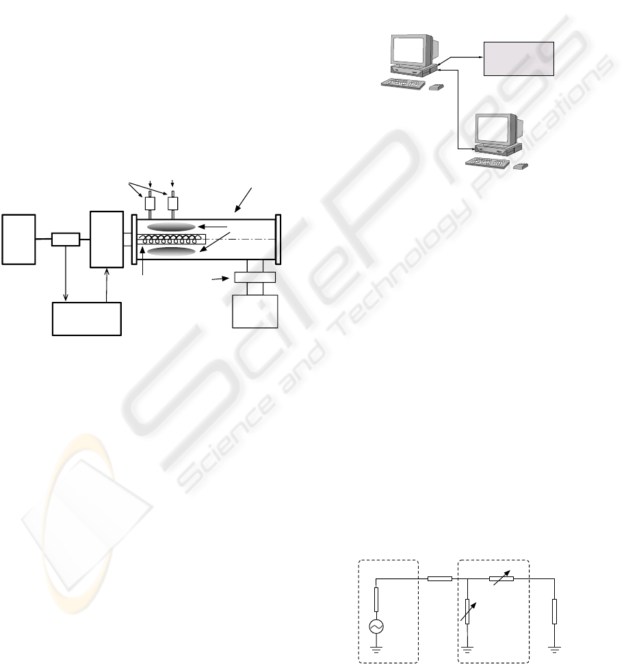
2.1 Plasma Discharge Chamber
The plasma discharge chamber is a stainless steel
cylindrical vacuum chamber of internal diameter
200mm and length 900mm (Fig.1). The helical an-
tenna is placed along the axis of the chamber, inside
a sealed 50mm diameter quartz tube, in order to keep
it outside of the vacuum region. The gasses are in-
jected into the chamber by the mass flow controllers
and are evacuated through the gate valve using a vac-
uum pump. The pressure at which the plasma is ig-
nited is usually between 10mTorr and 100mTorr, and
it is regulated by adjusting the position of the gate
valve and the gas flows.
2.2 RF Power Supply
The RF power generator is the ACG-10B made by
MKS Instruments, which can deliver a maximum of
1000W at a frequency of 13.56 MHz into a 50Ω load.
2.3 Plasma Process Monitoring and
Control
The control of the plasma process is achieved using
the Matlab xPC Target anvironment. This system
is composed of two PCs, one running Windows XP
(Host PC) and the other one running the real time xPC
Target operative system (Target PC) as in Fig.2. The
RS232 (TCP/IP)
Analog & Digital
Host PC
BARIS Plasma System
Interfaces
Target PC
Figure 2: Matching network schematic.
Target PC is equipped with analog and digital inter-
faces in order to read data from sensors and control
actuators and other devices. The role of the Host PC
is to upload the software to be executed in real time by
the Target PC, to start it, stop it and to monitor it while
running using the RS-232 interface. This kind of con-
figuration gives a considerable amount of computa-
tional power, allowing the implementation of com-
plex control algorithm for the plasma process (Ior-
danov et al., 2006).
2.4 Matching Network
The matching network transforms the plasma load
impedance (Z
PL
) into the Z
0
= 50Ω characteristic
impedance of the transmission line. It is a basic
“L” configuration (Fig.3) characterized by eq.(1) and
composed of “Load” (C
L
) and “Tune”(C
T
) variable
capacitors , both driven by servomotors.
Z
0
Z
L
Z
T
Z
PL
Z
Int
Z
0
=
RF Generator Matching Network
Figure 3: Matching network schematic.
IMPEDANCE MATCHING CONTROLLER FOR AN INDUCTIVELY COUPLED PLASMA CHAMBER - L-type
Matching Network Automatic Controller
203
Z
PL
=
Z
0
Z
L
Z
0
+ Z
L
+ Z
T
∗
=
Z
0
(1+ ω
2
Z
2
0
C
2
L
)
+ j
(1+ ω
2
Z
2
0
C
L
(C
L
+C
T
))
ωC
T
(1+ ω
2
Z
2
0
C
2
L
)
∗
(1)
with:
Z
T
=
1
jωC
T
, Z
L
=
1
jωC
L
, ω = 2π13.56·10
6
rad/s
where [...]
∗
denotes complex conjugation and ω is the
circular frequency.
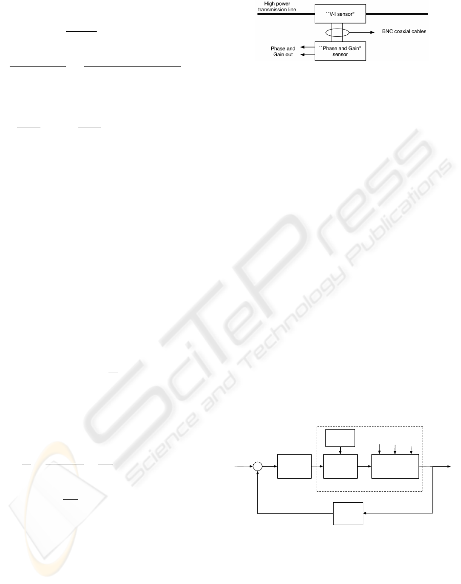
3 SENSOR
The impedance sensor is based on the Analog Devices
AD8302 phase and gain detector, which gives infor-
mation about the amplitude ratio and the phase differ-
ence between two signals. The inputs of the circuit
are two sinusoidal signals proportional to the volt-
age and the current waves in the power line respec-
tively. By measuring the ratio between voltage and
current and their phase difference, it is possible to cal-
culate the impedance or the reflection coefficient. The
impedance of a load connected in a transmission line
is defined as (2),
Z
L
=
V
0
I
0
(2)
where V
0
and I
0
are the vectors of voltage and cur-
rent respectively measured on the load and Z
L
the load
impedance. The last expression can be written using
the vectors in the exponential form as in (3):
Z
L
=
V
0
I
0
=
|V
0
| · e
jθ
V
|I
0
| · e
jθ
I
=
|V
0
|
|I
0
|
·e
j(θ
V
−θ
I
)
= G· e
∆θ
(3)
G =
|V
0
|
|I
0
|
∆θ = (θ
V
− θ
I
)
where G is the ratio between the voltage and the
current magnitudes and ∆θ is the phase difference be-
tween voltage and current waves. The impedance sen-
sor provides two analog signals that are proportional
to G and ∆θ. This device is divided in two parts,
the “V-I Sensor” and the “Phase and Gain Sensor”,
each one enclosed in a shielded aluminum box in or-
der to attenuate the effect of radio frequency distur-
bances (Fig.4). The former is connected along the
high power transmission line, and supplies two sig-
nals proportional to the voltage and the current of the
Figure 4: Block schematic of the impedance sensor.
main line. The “Phase and Gain Sensor” takes the
output signals of the “V-I Sensor” and provides their
phase difference and amplitude ratio. At the inputs of
the AD8302 there are two integrated low pass filters
(MINI-CIRCUITS SCLF-10.7) in order to remove the
harmonics components.
4 CONTROLLER
The main property required of the controller is global
convergence, that is the ability to drive the capaci-
tors to the matching point from any starting condition.
A model of the plasma impedance has been studied
(Keville et al., 2006), but it is quite complicated, not
suitable for the problem of the impedance matching
because it is computationally demanding. The dy-
namics of the plasma process are stable and time in-
variant, in addition the part related to the RF power
delivered P
D
(Fig.5) is much faster than the dynamic
of the matching unit, therefore it has been decided to
consider the variation of the plasma impedance during
the matching as a static disturbance. In this case the
only dynamics terms considered in the system are due
to the servomotors described by G(s). Considering
Controller
Matchbox
G(s)
Imp
sensor
+
-
RF
generator
Plasma
Ar
flow
O2
flow
Gate
Valve
BARIS
PD
Figure 5: Block schematic of the BARIS.
the magnitude of the reflection coefficient |Γ| as a
function of the capacitorsC
L
andC
T
, for a given value
of the load impedance (Z
PL
), using (1) is possible to
plot the graph in Fig.6. The main characteristic of this
function is that there is only one critical point corre-
sponding to the global minimum, that is the matching
point (|Γ| = 0). In this situation, the control problem
ICINCO 2007 - International Conference on Informatics in Control, Automation and Robotics
204
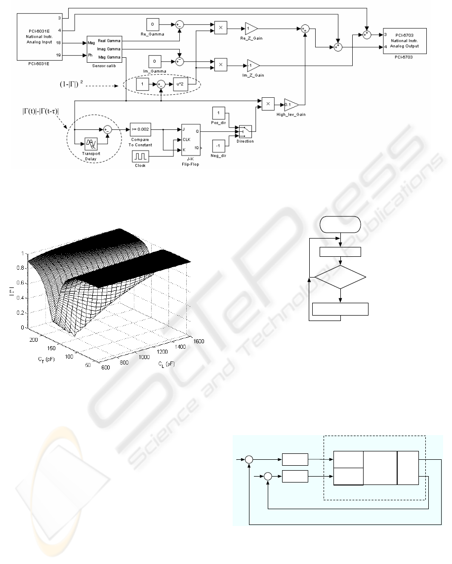
Figure 8: Simulink implementation of the hierarchical controller.
Figure 6: |Γ| as function of (C
L
,C
T
).
can be considered as a function minimization prob-
lem. A first possible approach can be to drive the
capacitors in the opposite direction of the gradient
of |Γ|, but the plasma impedance is variable and its
value it is unknown, therefore it is not possible to cal-
culate this vector. From Fig.6 is possible to see that
|Γ| is significantly more sensitive respect to C
T
than
C
L
. We have decided to use a hierarchical structure
composed of two parts: a coarse and a fine tune con-
troller. The coarse controller brings the system close
to the matching point, where the fine tune controller
takes over and drives the capacitors to the final po-
sition. The coarse controller is based on an iterative
minimization algorithm for |Γ| respect toC
T
, as in the
flow chart in fig.7. At regular intervals of time δ it
checks if the reflection coefficient and if it is increas-
ing, it inverts the direction of movement ofC
T
. When
Start
Wait !c
|!(t)|>|!(t-")|
Change CT direction
YES
NO
Figure 7: Iterative minimum search algorithm flow chart.
the system is approaching to the matching point there
is a smooth transition between the coarse controller
and the fine tune controller. The fine tune controller
is a dual SISO proportional controller (Fig.9) in which
C
L
is driven by Im[Γ] and C
T
is driven by Re[Γ].
BARIS
Load Cap
Imp.
sensor
Tune Cap
MatchBox
0
0
+
+
-
-
Re[
Γ]
Im[
Γ]
Plasma
SISO
SISO
Figure 9: Block schematic of the fine tune controller.
4.1 Implementation
Fig.8 illustrates the Simulink implementation of the
controller. The AD converter provides measurements
IMPEDANCE MATCHING CONTROLLER FOR AN INDUCTIVELY COUPLED PLASMA CHAMBER - L-type
Matching Network Automatic Controller
205
of G and ∆θ at a sampling period of δ
f
= 20mS,
which is also the sampling rate used by the fine tune
controller. The coarse controller uses a sampling pe-
riod of δ
c
= 100mS. |Γ| is determined via eq (4) by
the fine tune controller, allowing the delayed value of
|Γ(t − τ)| to be available at the δ
c
sampling instants
(τ = 4δ
f
).
Γ =
Z
L
− Z
0
Z
L
+ Z
0
(4)
The coarse controller checks the variation of the re-
flection coefficient |Γ(t)| − |Γ(t − τ)|. If it is increas-
ing, the J-K flip-flop inverts the direction of move-
ment of C
T
. Since the speed of C
T
is proportional to
|Γ|, the controller can be considered as a proportional
controller. The gains of the fine tune SISO controllers
are multiplied by (1− |Γ|)
2
in order to reduce its ef-
fect in the non-convergence region, in which it tends
to drive the capacitors in the wrong direction. In this
way, when approaching to impedance matching con-
dition, |Γ| is decreasing and (1 − |Γ|)
2
is increasing,
and there is a smooth transition from the coarse to the
fine tune controller.
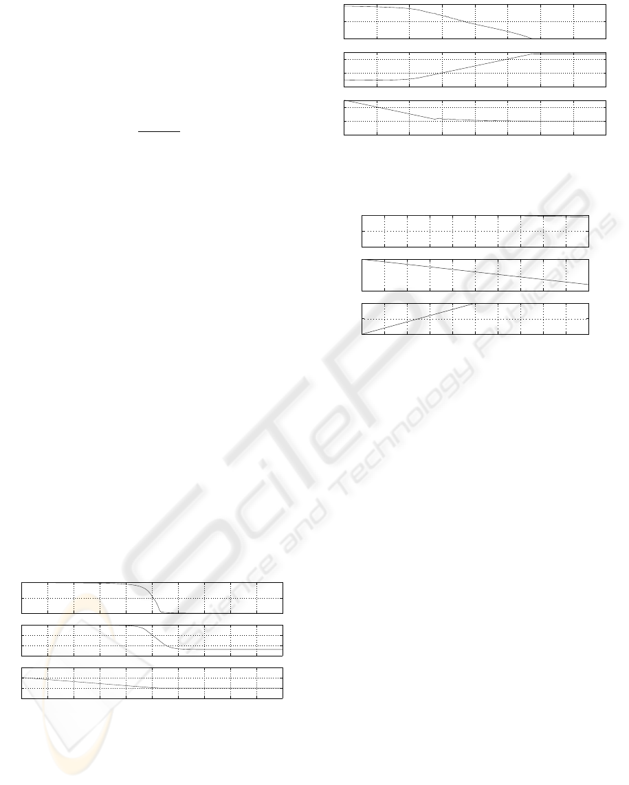
5 RESULTS
The controller has been tested both in simulation and
in the BARIS chamber. The simulation has been
performed using constant loads, and giving different
starting positions for the capacitors. Figs.10 and 11
show that the system converges both when the ini-
tial conditions are close and far away to the match-
ing point, that is the controller drives the capacitors in
the right direction in order to minimize |Γ|. Fig.12
0 1 2 3 4 5 6 7 8 9 10
0
0.5
1
| Γ |
0 1 2 3 4 5 6 7 8 9 10
4.7
4.8
4.9
Load pos (V)
0 1 2 3 4 5 6 7 8 9 10
1
2
3
4
Time (s)
Tune pos (V)
Figure 10: Simulation results with starting conditions close
to the matching point.
shows the behavior of the system when the fine tune
controller’s gains are not multiplied by (1 − |Γ|)
2
;
for a starting condition far away from the matching
point there is no convergence. In this case the coarse
controller can’t take over and the fine tune controller
drives the capacitors in the wrong direction.
0 5 10 15 20 25 30 35 40
0
0.5
1
|Γ|
0 5 10 15 20 25 30 35 40
0
2
4
Load pos (V)
0 5 10 15 20 25 30 35 40
0
2
4
Time (s)
Tune pos (V)
Figure 11: Hierarchal controller with starting conditions far
away from the matching point.
0 2 4 6 8 10 12 14 16 18 20
0
0.5
1
| Γ |
0 2 4 6 8 10 12 14 16 18 20
0
5
Load pos (V)
0 2 4 6 8 10 12 14 16 18 20
3
4
5
Time (s)
Tune pos (V)
Figure 12: Hierarchical controller, with no fine tune con-
troller gain attenuation.
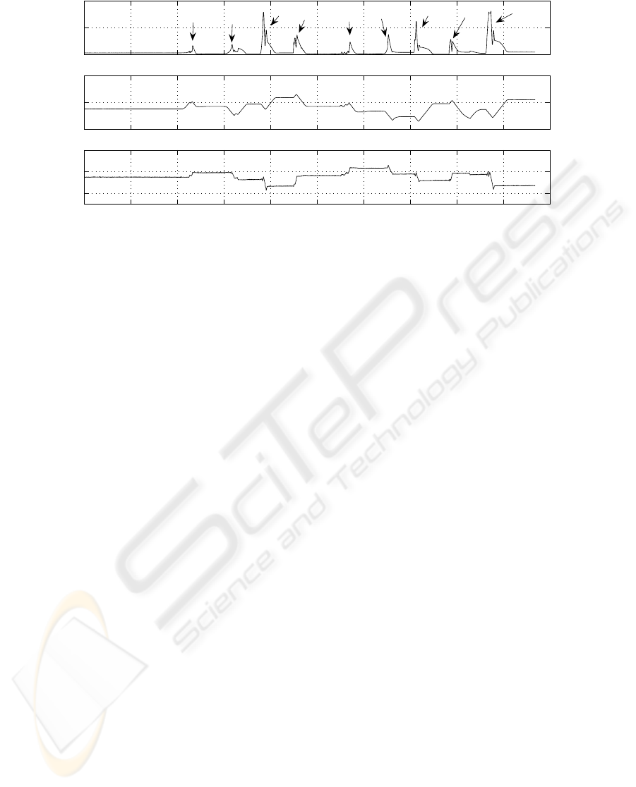
The controller has been tested also in the BARIS sys-
tem; this test has been performed using step func-
tions for the plasma variables (RF power, pressure, A
r
and O
2
flows). From the results of this test (Fig.13)
it is possible to see that each time the plasma state
changes, the controller tunes the matching network,
minimizing the magnitude of the reflection coefficient
|Γ|. In particular, mark A denotes a step in RF power,
mark B denotes a step in the gate valve position, mark
C denotes a step in O
2
flow and mark D denotes a step
in A
r
flow.
6 CONCLUSION
The hierarchical controller shows good performances
regarding the convergence. Besides, it is computa-
tionally not demanding, giving the possibility to be
implemented using a simple micro-controller. A mul-
tivariable controller, which observes the dependance
of Im[Z
PL
] on both C
L
and C
T
was also designed, but
requires an extensive look-up table and matrix inver-
sion, which is in stark contrast to the attractive sim-
plicity of the final controller presented above. The
underlying principle of the controller is based only
on the matching network structure, therefore it can be
implemented also in other applications using a similar
“L-type” matching network.
ICINCO 2007 - International Conference on Informatics in Control, Automation and Robotics
206
0 10 20 30 40 50 60 70 80 90 100
0
0.5
1
|Γ|
0 10 20 30 40 50 60 70 80 90 100
1
2
3
Load pos (V)
0 10 20 30 40 50 60 70 80 90 100
3.6
3.8
4
Time (s)
Tune pos (V)
A
A
A
B
B
C
C
D
D
Figure 13: Experimental measurements in the BARIS.
ACKNOWLEDGEMENTS
The authors are grateful for the financial support of
the Irish Research Council for Science Engineering
and Technology (IRCSET) and INTEL Ireland Ltd.
REFERENCES
Cottee, C.J.; Duncan, S. (2003). Design of matching circuit
controllers for radio-frequency heating. IEEE Trans-
actions on Control Systems Technology, 11(1):91–
100.
De Mingo, J., Valdovinos, A., Crespo, A., Navarro, D., and
Garcia, P. (2004). An RF electronically controlled
impedance tuning network design and its application
to an antenna input impedance automatic matching
system. IEEE Transactions on Microwave Theory and
Techniques, 52(2):489–497.
Ida, I., Takada, J., Toda, T., and Oishi, Y. (2004a). An
adaptive impedance matching system and considera-
tions for a better performance. IEEE 5th International
Symposium on Multi-Dimensional Mobile Communi-
cations Proceedings, 2:563–567.
Ida, I., Takada, J., Toda, T., and Oishi, Y. (2004b). An adap-
tive impedance matching system and its application to
mobile antennas. IEEE Region 10 Conference, 3:543–
546.
Ida, I., Takada, J., Toda, T., and Oishi, Y. (2004c). An adap-
tive impedance matching system for mobile commu-
nication antennas. IEEE Antennas and Propagation
Society International Symposium, 3:3203–3206.
Iordanov, P., Keville, B., Ringwood, J., and Doherty, S.
(2006). On the closed-loop control of an argon plasma
process,. Irish Signals and Systems Conference.
Keville, B., Iordanov, P., Ringwood, J., Doherty, S.,
Faulkner, R., Soberon, F., and McCarter, A. (2006).
On the modeling and closed loop control of an induc-
tively coupled plasma chamber. IFAC Workshop on
Advanced Process Control for Semiconductor Manu-
facturing.
Mazza, N. (1970). Automatic impedance matching system
for RF sputtering. IBM Journal of Research and De-
velopment, 14(2).
Moritz, J. and Sun, Y. (2001). Frequency agile antenna tun-
ing and matching. IEE Eighth International Confer-
ence on HF Radio Systems and Techniques, 148:177–
182.
Parro, V. and Pait, F. (2003). Design of an automatic
impedance matching system for industrial continuous
microwave ovens. Sociedade Brasileira de Microon-
das Optoeletronica/IEEE Microwave and Optoelec-
tronics Conference, 2:20–23.
Sun, Y. and J.K., F. (1997). Component values ranges of
tunable impedance matching networks in rf commu-
nications systems. IEE HF Radio Systems and Tech-
niques, 441.
Sun, Y. and J.K., F. (1999). Antenna impedance matching
using genetic algorithms. IEE National Conference on
Antennas and Propagation, 441:31–36.
Thompson, M. and Fidler, J. (2000). Application of
the genetic algorithm and simulated annealing to LC
filter tuning. IEE Circuits, Devices and Systems,
474(2):169–174.
Vai, M. and Prasad, S. (1993). Automatic impedance
matching with a neural network. IEEE Microwave and
Guided Wave Letters, 3(10).
IMPEDANCE MATCHING CONTROLLER FOR AN INDUCTIVELY COUPLED PLASMA CHAMBER - L-type
Matching Network Automatic Controller
207
