
EVALUATION OF STRUCTURAL PROPERTIES FOR BUSINESS
PROCESSES
Vladimír Modrák
Faculty of Manufacturing Technology, Technical University of Košice,Bayerova 1, Prešov , Slovakia
Keywords: Structural properties, Business process, Redesign, Diagram
Abstract: This paper describes the issue of the evaluation of processes designed on the principles of reengineering.
Especially business process structures on high-level modelling are subjected that substantially support the
company’s successful running. Presented analysis and assessment put emphasis on the structural properties
of business processes.
For evaluation such tools as comparing of quantitative indicators of business
processes are used.
1 INTRODUCTION
One of the important roles of BPR is building of
unified logistic concept of organisation, which
should involve co-ordination and management of all
material and information flows. This concept is
based on mapping and classification of processes
that representing the core of Business Process
Reengineering (BPR). In present BPR activities
converge on modelling and processes analysis and as
a result the principal activities are aimed at the
processes, strategy, managerial information systems
and changes in control [Earl, 1993]. In the
following, the contribution outlines the procedure
applied to modelling of business processes, on the
basis of that deals with the set of quantitative
indicators used for analysing and redesigning
structural properties of business processes.
2 PROCESS CLASSIFICATION IN
TERMS OF BUSINESS PROCESS
REDESIGN
From the methodical point of view the process
redesign requires in the first place revision of
existing processes in terms of their effectiveness,
and verifying of their mutual connections. Further
stage involves a draft a new arrangement of
processes, which should be carried out either on the
basis of empiricism, or on a certain systematic basis.
The business process redesign requires also explicit
classification basis by which processes can be
represented by classes.
The classification that will be analyzed further had
come out from these following basic reengineering
principles:
P1: In the overall arrangement of processes it is
suitable to combine elements of decentralization
with elements of centralization;
P2: Specification of the substance of the process
at a certain level has to be as precise as
possible;
P3: In the arrangement of processes the
minimizing of the number of hierarchical levels
is needed take into account.
On the basis of the above, the classification
framework for systematic rebuilding of processes
can be built from three hierarchical levels, which are
(from down to top):
- Elementary process (EP) that is represented by a
set of complex tasks, consisting from smallest
elements-activities;
- Integrated process (IP), which represents a set of
two or more elementary processes with the purpose
to create the autonomic organizational unit of on
second hierarchical level;
- Unified enterprise process (UEP), which consists
of one or several integrated processes at the extent
that is conditioned by its capability to flexibly and
effectively secure customers’ requirements
619
Modrák V. (2004).
EVALUATION OF STRUCTURAL PROPERTIES FOR BUSINESS PROCESSES.
In Proceedings of the Sixth International Conference on Enterprise Information Systems, pages 619-622
DOI: 10.5220/0002609706190622
Copyright
c
SciTePress
As it is evident processes and their elements by
these classification are clustered in hierarchical
manner into classes and subclasses. Naturally,
process models have to be understood by different
levels of management. Managers of higher level
may not need to know each detail about the process,
but they may want to get an overview about the
overall process landscape [G&W, 1999]. Process
landscaping avoids these problems by identifying
core processes and by describing how process
models are related. These aspects are outlined in the
next section.
3 BUSINESS PROCESS REDESIGN
When specifying the process as an object of
modelling, we also start from the requirement of
monitoring its value-adding function. Then as parts
of commodity flows there are also information
flows. They are realized in the control of processes,
but they are essential for a pricing the commodities
and costs in financial units. Since, by gathering
information, a large number of sizable files are
created, it is not necessary in this stage to reflect
them explicitly into models of the processes in the
conceptual stage. In the proposed procedures, they
can be therefore given the role of a ‘shadow’, which
is unveiled when making a concept of data models.
Tools for their modelling are, for example, data flow
diagrams (built bottom-up), which in the stage of
drafting an information system, they should copy the
hierarchical and content structure of commodity
flow diagrams and extract their information flows
and procedures from them. The application of
classification approach in the modelling of
organisational context of business processes is
further shown on the procedure, which has been
inspired from more methods [C&Y, 1990], [SVD,
1993].
From the carried out analysis of methodologies of
designing information systems, Structured System
Analysis and Design Method (SSADM) [A&G,
1990] and the Object Modelling Technique (OMT)
[RBP, 1991] were most compatible with the
proposed procedure based on the Structured Process
Decomposition (SPD). In contrast with a structured
analysis, in which the cardinal modelling tools are
data flow diagrams and other additional diagrams,
the procedure of SPD consists of a set of tools,
which are:
- system diagram,
- context diagram,
- commodity flow diagrams,
- state transition diagrams.
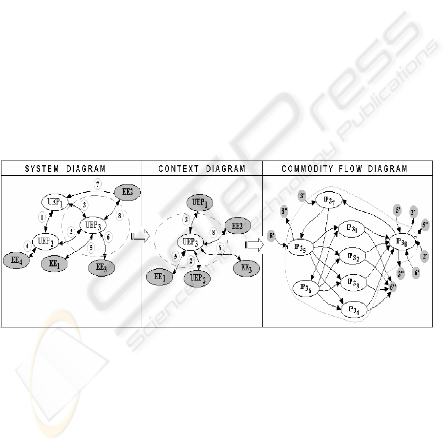
The sequence of the first three diagrams with the
links between individual modeling levels is shown in
figure 1.
4 STRUCTURAL PROPERTIES
ANALYSIS ON THE
HORIZONTAL LEVEL
Within the outlined models of the business processes
by the help of the SPD method, individual diagrams
were designed based on the principles of the graphs
theory. In order to design such models, a complete
amount of information about the reality that is being
modelled is not required. However, considering
reengineering, we have to take into consideration the
structural properties of the process. They should be
Figure 1: The example of the sequence of diagrams
ICEIS 2004 - INFORMATION SYSTEMS ANALYSIS AND SPECIFICATION
620

investigated by means of a topological structure
analysis in terms of which the basic elements of the
process structure – nodes and links are the subject of
investigation. As a rule, the starting point of this
analysis is the linkage matrix of a graph expressed
by notation V = ⏐ v
ij
⏐. According to this matrix,
each node “k” (k = 1, 2,…,n), where “n” is the
number of nodes in the graph, corresponds to a
vector v(k) = (v
k
, v
k
) with following components :
∑
=
=
n
1j
kjk
vv
∑
=
=
n
1i
ik
k
vv
In accordance with the previous relations, symbol
“v
k
” represents the number of the matrix elements of
the k-th line and “v
k
” is the number of elements of
the k-th column of the linkage matrix. Then, for the
isolated node, it is valid this precondition: v
k
= v
k
= 0.
4.1 Structure binding
Of several possible indicators of the complexity of
the business processes structure, the ‘redundancy”
degree of the structure linkage can also be
considered useful. This is based on the concept of
the graph binding, which means the least possible
number of the linkage graph, the reduction of which
would lead to the graph unbinding which contains
isolated nodes. When the graph consists of “n” links,
then graph binding is possible if
1nL
min
−= (1)
which is valid for both oriented and non-oriented
graphs.
In order to determine the degree of binding
structure “B”, the following indicator expressing a
relative measure of the size of the number of the “L”
links that occur within a given structure can be
applied:
min
min
L
LL
B
−
=
(2)
With the oriented graphs, each link (i,j) has one
element in the linkage matrix v
ij
= 1. Within the non-
oriented graph, each link has two elements, where it
is valid v
ij
= v
ji
. With the minimum number of links,
the value of this relation equals zero.
In connection to the described processes modelling
techniques, the indicator of the structure binding can
be used with the analysis of the processes structure
of the UEP type that are represented by means of
Commodity flow diagrams of the first degree. For
the purpose of analysis, only internal structure of the
investigated process is relevant, where the relations
of the process to its immediate environment are not
taken into consideration. In order to apply the given
indicator, the process structure UEP
3
will be taken
into account. The structure, which was obtained
based on the diagram in Figure 1, is shown in Figure
2 a The index value of the structure binding “B” of
the given process, when L = 13 and L
min
= 7 by
formula (2) equals 1,14. The reduction of the
structure linkage can be obtained by the purposeful
integration of the matter in hand joinable processes
either sequentially or parallel arranged. This
integration is in conformity with the principles of
reengineering, according to for instance [H&C,
1993; R&U, 1996]. In this case, the integration of
the processes IP3
1
all the way to IP 3
4
will be
applied to the process IP 3
1-4
and similarly
IP 3
7
and IP 3
8
will be applied to the process IP 3
7-8
based on which the new process structure seen in
Figure 2b will be obtained. The index value obtained
by this transformation will be reduced to B= 0,66.
4.2 Structure diameter
The Structure diameter is another indicator used to
compare the structural characteristics of the process.
This indicator can be formally expressed under the
following suppositions:
C1: Let “dij” be the length of the minimum path
between the node “i” (from which the linkage was
initiated) and the node “j” ( in which the
performance of the network graph finishes)
expressed by the number of links which the path
consists of.
C2: Let “I” and “J” represent the number of input
and output nodes.
Then the structure diameter can be expressed by the
relation:
,Jj,Ii,dmaxD
ij
∈∈=
( 3)
which characterizes the maximum number of
linkage separating the initial and target structure
elements.
Figure 2: The example of internal process structure
linkage reduction
EVALUATION OF STRUCTURAL PROPERTIES FOR BUSINESS PROCESSES
621

When applying this indicator to the same process as
with the previous case, it is necessary to consider the
structure of the given process that includes the
elements of the environment, which are in a direct
interaction with the elements of the internal structure
of the process.
With the process analysis, using this indicator we
will consider the initial state the original structure of
the UEP
3
process that is shown in Figure 2a that
contains also the elements with which the given
process is in interaction. The structure defined in
such a way can be seen in Figure 3 (left-hand).
Then for I={2’, 3’, 5’, 6’, 8’} and J={2’’, 3’’, 5’’,
6’’, 8’’} we obtain: max d
ij
= d
2’6’’
= d
3’2’’
= d
3’3’’
=
d
3’5’’
= d
5’6’’
=. D
6’6’’
= 5, thus D = 5.
A lower value of this indicator for the given process
can be obtained again by the purposeful integration,
which is represented by the joining of sequentially
arranged processes IP 3
7
and IP 3
8
to the process IP
3
7-8
and the joining of the processes IP3
1
all the way
to IP 3
4
to the process IP 3
1-4
. Through such a
modification of the process structure, the process
model presented in Figure 3 (right-hand) can be
obtained. The Diameter of the structure for the
structure of the same process modified by the
integration and extended by the elements with which
the given process is in an interaction (Figure 3b) can
be calculated in the same way. The number of the
graph nodes “I” and “J” does not change.
Based on this, it is obvious that the new value D = 4.
It affirms obtaining the process simplification from
the viewpoint of the number of the one after another
links controlled autonomously.
5 CONCLUSION
Structural business process metrics seems to be also
very helpful especially in choosing a meaningful
target for process improvement during the
reengineering activities. The position of this kind of
metrics is looking for its stable place in the practical
steps of BPR, because the analysis and assessment
of business process structures are critical in
achieving enhanced effectiveness of business
processes.
ACKNOWLEDGEMENT
"This work was supported (in part) by a grant from
VEGA ME SR and SAS, No. 1/1241/04”.
REFERENCES
Ashworth, C, Goodland, M. (1990). SSADM: A Practical
Approach, McGraw-Hill.
Coad, P., Yourdon, E. (1990). Object-Oriented Analysis,
Englewood Cliffs NJ, Prentice-hall.
Earl, M. J. (1993). Experiences in Strategic Information
Planning, MIS Quarterly, March Vol. 17:1, pp 1-24 .
Gruhn V., Wellen U. (1999). Process Landscaping:
Modelling Complex Business Processes, European
Journal of Engineering for Information Society
Applications, Volume 1, Issue 3, 1999, pp. 1-22.
Hammer, M., Champy, J. (1993). Reengineering the
Corporation: A Manifesto for Business Revolution,
HarpperCollins Publishers, Inc., New York.
Robson, M., Ullah, P. (1996). A practical guide to
business process re-engineering, Gower Publishing
limited, Aldeshort , Hampshire, England.
Rumbaugh, J.E., Blaha, M Premerlani, W.J. Eddy, F.
Lorensen, W. (1991). Object-Oriented Modelling
and Design, Prentice Hall International, Inc..
Sambamurthy, V., Venkataraman, S., Desactis, G.(1993):
The design of Information Technology Planning
Systems for Varying organizational context.
European Journal of Information Systems, Vol. 2
No. 1, 1993, pp. 23-35.
Figure 3: The example of internal and external
process structure linkage integration
ICEIS 2004 - INFORMATION SYSTEMS ANALYSIS AND SPECIFICATION
622
